DS1861B+ Maxim Integrated Products, DS1861B+ Datasheet - Page 24
DS1861B+
Manufacturer Part Number
DS1861B+
Description
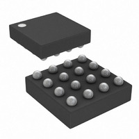
IC LASR CTRLR 1CHAN 5.5V 16CSBGA
Manufacturer
Maxim Integrated Products
Type
Laser Diode Controller (Fiber Optic)r
Datasheet
1.DS1861E.pdf
(25 pages)
Specifications of DS1861B+
Number Of Channels
1
Voltage - Supply
2.85 V ~ 5.5 V
Current - Supply
5mA
Operating Temperature
-40°C ~ 95°C
Package / Case
16-CSBGA
Mounting Type
Surface Mount
Lead Free Status / RoHS Status
Lead free / RoHS Compliant


Before calibrating, the APC register should be set to a
low value to ensure the laser’s maximum power level is
not exceeded before the power level is calibrated.
Additionally, the ER register should be set to its mini-
mum value (28 decimal) to ensure that a data test pat-
tern does not cause the laser to shut off. Once the APC
and ER registers are at minimal values, enable a data
pattern and calibrate the average power level first.
While sending data through the laser diode, increase
the value in the APC register until the light output
matches the desired average power level. The average
power level is the arithmetic average of the 1 and 0
power levels.
While sending data through the laser diode, begin
increasing the ER register from its minimum value of 28
decimal (1Ch), until the proper extinction ratio is
reached or the maximum setting (104 decimal or 68h)
of the low range is reached. If the maximum low range
value is reached, write the ER register to 156 decimal
(9Ch), which switches the extinction ratio value to the
minimum value of the high range. Continue increasing
the ER setting until the proper extinction ratio is
reached. If the maximum value of the high range set-
ting is reached (232 decimal or E8h) without reaching
the proper extinction ratio, then either the desired
extinction ratio cannot be reached or a problem is pre-
venting the system from operating properly.
Full Laser Control with Fault Management
24
____________________________________________________________________
Calibrating APC and Extinction Ratio
Applications Information
Calibrating the Average Power Level
Calibrating the Extinction Ratio
Up to eight DS1861s can be addressed on a single I
bus by using the device’s address inputs (A
change its slave address. For information about device
addressing, see the I
To achieve best results, it is recommended that the power
supply is decoupled with a 0.01µF or a 0.1µF capacitor.
Use high-quality, ceramic, surface-mount capacitors, and
mount the capacitors as close as possible to the V
GND pins to minimize lead inductance.
The BMD shunt capacitor works with the internal resis-
tance of the BMD input to provide a lowpass filter that
reduces the effects of noise on the APC loop. Its
capacitance value must be chosen carefully to ensure
that it is both large enough to provide good filtering of
high-frequency noise and small enough that it does not
cause the control loop to become unstable. A 1nF, 10%
tolerant, X7R ceramic capacitor is recommended.
SDA is an open-collector bidirectional data pin on the
DS1861 that requires a pullup resistor to realize high
logic levels. Either an open-collector output with a
pullup resistor or a push-pull output driver can be used
for the SCL input. Pullup resistor values should be cho-
sen to ensure that the rise and fall times listed in the AC
Electrical Characteristics table are within specification.
SDA and SCL Pullup Resistors
Addressing Multiple DS1861s
2
C Communications section.
Power-Supply Decoupling
on a Common I
BMD Shunt Capacitor
2
, A
2
1
C Bus
, A
CC
0
and
) to
2
C
Related parts for DS1861B+
Image
Part Number
Description
Manufacturer
Datasheet
Request
R

Part Number:
Description:
Ds1861 Full Laser Control With Fault Management
Manufacturer:
Maxim Integrated Products, Inc.
Datasheet:

Part Number:
Description:
MAX7528KCWPMaxim Integrated Products [CMOS Dual 8-Bit Buffered Multiplying DACs]
Manufacturer:
Maxim Integrated Products
Datasheet:
Part Number:
Description:
Single +5V, fully integrated, 1.25Gbps laser diode driver.
Manufacturer:
Maxim Integrated Products
Datasheet:
Part Number:
Description:
Single +5V, fully integrated, 155Mbps laser diode driver.
Manufacturer:
Maxim Integrated Products
Datasheet:
Part Number:
Description:
VRD11/VRD10, K8 Rev F 2/3/4-Phase PWM Controllers with Integrated Dual MOSFET Drivers
Manufacturer:
Maxim Integrated Products
Datasheet:
Part Number:
Description:
Highly Integrated Level 2 SMBus Battery Chargers
Manufacturer:
Maxim Integrated Products
Datasheet:
Part Number:
Description:
Current Monitor and Accumulator with Integrated Sense Resistor; ; Temperature Range: -40°C to +85°C
Manufacturer:
Maxim Integrated Products
Part Number:
Description:
TSSOP 14/A�/RS-485 Transceivers with Integrated 100O/120O Termination Resis
Manufacturer:
Maxim Integrated Products
Part Number:
Description:
TSSOP 14/A�/RS-485 Transceivers with Integrated 100O/120O Termination Resis
Manufacturer:
Maxim Integrated Products
Part Number:
Description:
QFN 16/A�/AC-DC and DC-DC Peak-Current-Mode Converters with Integrated Step
Manufacturer:
Maxim Integrated Products
Part Number:
Description:
TDFN/A/65V, 1A, 600KHZ, SYNCHRONOUS STEP-DOWN REGULATOR WITH INTEGRATED SWI
Manufacturer:
Maxim Integrated Products
Part Number:
Description:
Integrated Temperature Controller f
Manufacturer:
Maxim Integrated Products
Part Number:
Description:
SOT23-6/I�/45MHz to 650MHz, Integrated IF VCOs with Differential Output
Manufacturer:
Maxim Integrated Products
Part Number:
Description:
SOT23-6/I�/45MHz to 650MHz, Integrated IF VCOs with Differential Output
Manufacturer:
Maxim Integrated Products
Part Number:
Description:
EVALUATION KIT/2.4GHZ TO 2.5GHZ 802.11G/B RF TRANSCEIVER WITH INTEGRATED PA
Manufacturer:
Maxim Integrated Products