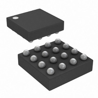
DS1861B+ Maxim Integrated Products, DS1861B+ Datasheet - Page 17

DS1861B+
Manufacturer Part Number
DS1861B+
Description
IC LASR CTRLR 1CHAN 5.5V 16CSBGA
Manufacturer
Maxim Integrated Products
Type
Laser Diode Controller (Fiber Optic)r
Datasheet
1.DS1861E.pdf
(25 pages)
Specifications of DS1861B+
Number Of Channels
1
Voltage - Supply
2.85 V ~ 5.5 V
Current - Supply
5mA
Operating Temperature
-40°C ~ 95°C
Package / Case
16-CSBGA
Mounting Type
Surface Mount
Lead Free Status / RoHS Status
Lead free / RoHS Compliant
communicate over the I
cuitry to function properly. The first monitoring level, the
power-on digital voltage (V
functionality when V
monitoring level is the power-on analog voltage (V
The DS1861 disables I
asserts the TX-F output whenever V
Both V
to force the chip to function when V
quate level to assure the DS1861 operates properly.
The high and low transmit power quick-trip thresholds
are each programmed by 3 bits that select one of
seven different levels as a function of the expected
I
gramming all three bits to zero. Disabling a QT by pro-
gramming its control bits to zero prevents the QT alarm
flags from ever being set, which consequently prevents
that monitor from asserting the TX-F output, latching the
device into a shutdown condition, or setting the alarm
bits in the Status register. The HTXP and LTXP enable
bits can be used to prevent the transmit power level
QTs from causing shutdown while allowing the TX-F
output to be set to flag the system of a transmit power
fault condition. Figure 13 shows the shutdown logic.
Tables 1 and 2 show the QT thresholds as a function of
I
The high-bias, quick-trip alarm features an 8-bit thresh-
old setting with an LSB of 8.2µA. Programming the
HBIAS threshold to zero inhibits the HBIAS alarm flag,
preventing TX-F from being asserted, the HBIAS alarm
from causing a shutdown, and the HBIAS alarm bit in
Status from being set. The HBIAS enable bit can be
used to prevent shutdown from occurring while allow-
ing the HBIAS alarm flag to trigger TX-F.
The DS1861 has two 16-bit password entry registers
(used as a 32-bit value) and two 16-bit password regis-
ters (used as 32-bit value) that can be used to write-pro-
tect all the configuration settings. The password entry
registers, PWE High and PWE Low, are the locations
where the user enters the password to disable the write
protection and change the device settings. The pass-
word bytes, PW High and PW Low, set the password to a
new value. When the device is write-protected, the only
bytes that can be written are the password entry bytes.
To secure the password, the PW bytes always read as
0s when the PWE bytes do not match the PW bytes.
Once the correct password has been entered into the
BMD
BMD
current. Each QT monitor can be disabled by pro-
current-set point.
CC
monitors are nonmaskable, so there is no way
Full Laser Control with Fault Management
CC
2
C bus and for the analog cir-
is below V
BIASSET
POD
Password Protection
), inhibits the part’s I
and I
CC
CC
POD
____________________________________________________________________
is not at an ade-
is below V
. The second
MODSET
POA
POA
and
2
C
).
.
PWE bytes, the password can also be read from the
PW registers. Because the PWE bytes can be read all
the time, it is recommended that the PWE bytes are
written to all 1s once the desired settings are modified
to prevent anyone from simply reading PWE to attain
the password. The PWE bytes are SRAM, so they reset
themselves to 1s if V
In addition to write protection, the password must also
be entered and the DS1861 must be HALTed to read
the I
Reading the BIASSET and MODSET Registers section
for more information about reading the DAC codes.
Table 1. HTXP Threshold Settings
*Disabled inhibits the HTXP QT from causing a shutdown or
asserting TX-F.
Table 2. LTXP Threshold Settings
*Disabled inhibits the LTXP QT from causing a shutdown or
asserting TX-F.
HTXP_Thresh<2:0>
LTXP_Thresh<2:0>
BIASSET
000
001
010
011
100
101
110
111
000
001
010
011
100
101
110
111
and I
CC
MODSET
drops below V
HIGH-TRANSMIT POWER
LOW-TRANSMIT POWER
THRESHOLD (I
THRESHOLD (I
DAC codes. See the
Do not use
Do not use
Disabled*
Disabled*
1.30
1.43
1.56
1.69
1.82
1.95
0.81
0.76
0.54
0.41
0.28
0.14
POA
.
SET
SET
)
)
17


