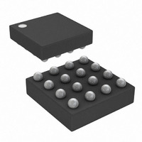
DS1861B+ Maxim Integrated Products, DS1861B+ Datasheet - Page 13

DS1861B+
Manufacturer Part Number
DS1861B+
Description
IC LASR CTRLR 1CHAN 5.5V 16CSBGA
Manufacturer
Maxim Integrated Products
Type
Laser Diode Controller (Fiber Optic)r
Datasheet
1.DS1861E.pdf
(25 pages)
Specifications of DS1861B+
Number Of Channels
1
Voltage - Supply
2.85 V ~ 5.5 V
Current - Supply
5mA
Operating Temperature
-40°C ~ 95°C
Package / Case
16-CSBGA
Mounting Type
Surface Mount
Lead Free Status / RoHS Status
Lead free / RoHS Compliant
The I
embedded 18-bit and 12-bit DACs, respectively, and
their output currents can be read when the DS1861 has
been halted using the halt bit, and the password has
been entered. See the Detailed Register Descriptions
section for information on calculating the output current
from the register’s value.
Figure 7. BMD Current Setpoint vs. APC Register Setting
Figure 8. AERC Block Diagram
BIASSET
1.500
1.125
0.750
0.375
Reading the BIASSET and MODSET
0
Full Laser Control with Fault Management
and I
0
DS1861
APC REGISTER SETTING (DECIMAL)
MODSET
64
BIASSET
MODSET
BMD
currents are generated by
128
I
I
I
BIASSET
MODSET
BMD
192
____________________________________________________________________
Registers
255
BIASREF
MODREF
LASER DRIVER
PHOTO-
DIODE
A
A
D
M
The DS1861 injects a small disturbance current to mea-
sure the gain (light/mA) of the laser driver and laser
diode pairing. This control methodology makes the
extinction ratio insensitive to changes in the photodi-
ode’s responsivity due to temperature and aging
effects, as long as the ratio of the laser driver’s bias
current gain (A
remains constant (Figure 8).
The disturbance current is automatically scaled as the
BMD current-set point is adjusted, so the peak distur-
bance current always increases I
3.3%. See Figure 9 for details.
To understand how the MODSET and BIASSET currents
control the extinction ratio, the extinction ratio equation
(extinction ratio = P1/P0) must first be expressed in
terms of the modulation power (P
power (P
levels that correspond to the optical logic 1 (P1) and
logic 0 (P0) levels.
MOD
BIAS
I
I
BIAS
MOD
Extinction Ratio
AVG
Automatic Extinction Ratio Control
). Figure 10 shows the current and power
AC-COUPLING
D
CIRCUITRY
) and modulation current gain (A
LIGHT
=
I
D
P
P
*
0
1
=
P
P
AVG
AVG
*I
LASER
DIODE
BMD
D
= I
MOD
BIAS
+
−
2
2
1
by approximately
1
± 1
P
P
) and average
MOD
MOD
2
I
MOD
13
M
)


