DS1874T+ Maxim Integrated Products, DS1874T+ Datasheet - Page 84
DS1874T+
Manufacturer Part Number
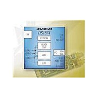
DS1874T+
Description
IC CTLR SFP+ ANLG LDD 28-TQFN
Manufacturer
Maxim Integrated Products
Type
Laser Diode Controllerr
Datasheet
1.DS1874TTR.pdf
(88 pages)
Specifications of DS1874T+
Number Of Channels
1
Voltage - Supply
2.85 V ~ 3.9 V
Current - Supply
2.5mA
Operating Temperature
-40°C ~ 95°C
Package / Case
28-WFQFN Exposed Pad
Mounting Type
Surface Mount
Number Of Outputs
5
Duty Cycle (max)
50 %
Output Voltage
0 V to 3.9 V
Mounting Style
SMD/SMT
Switching Frequency
0 KHz to 400 KHz
Operating Supply Voltage
2.85 V to 3.9 V
Supply Current
2.5 mA to 10 mA
Maximum Operating Temperature
+ 95 C
Fall Time
300 ns
Minimum Operating Temperature
- 40 C
Rise Time
300 ns
Synchronous Pin
Yes
Lead Free Status / RoHS Status
Lead free / RoHS Compliant
Other names
90-1874T+000


Table 02h, Register FDh: TXSTAT2
SFP+ Controller with Digital LDD Interface
Table 02h, Register FEh–FFh: RESERVED
Table 04h, Register 80h–C7h: MODULATION LUT
84
80h–C7h
______________________________________________________________________________________
FDh
FACTORY DEFAULT
READ ACCESS
WRITE ACCESS
MEMORY TYPE
These registers are reserved.
FACTORY DEFAULT
READ ACCESS
WRITE ACCESS
MEMORY TYPE
MAX3798/MAX3799 register. This value is read from the MAX3798/MAX3799 with the 3-wire interface every t
(see the MAX3798/MAX3799 electrical characteristics).
FACTORY DEFAULT
READ ACCESS
WRITE ACCESS
MEMORY TYPE
The digital value for the modulation DAC output.
The MODULATION LUT is a set of registers assigned to hold the temperature profile for the MODULATION
REGISTER. The values in this table determine the set point for the modulation voltage. The temperature
measurement is used to index the LUT (TINDEX, Table 02h, Register 81h) in 2°C increments from -40°C to
+102°C, starting at 80h in Table 04h. Register 80h defines the -40°C to -38°C MOD output, Register 81h defines
the -38°C to -36°C MOD output, and so on. Values recalled from this EEPROM memory table are written into the
MODULATION REGISTER (Table 02h, Register 82h–83h) location that holds the value until the next temperature
conversion. The DS1874 can be placed into a manual mode (MOD EN bit, Table 02h, Register 80h), where the
MODULATION REGISTER is directly controlled for calibration. If the temperature compensation functionality is
not required, then program the entire Table 04h to the desired modulation setting.
BIT 7
BIT 7
2
2
7
7
2
2
6
6
00h
PW2 or (PW1 and RWTBL246) or (PW1 and RTBL246)
PW2 or (PW1 and RWTBL246)
Nonvolatile (EE)
00h
Volatile
00h
PW2 or (PW1 and RWTBL246) or (PW1 and RTBL246)
N/A
Volatile
PW2 or (PW1 and RWTBL246) or (PW1 and RTBL246)
PW2 or (PW1 and RWTBL246)
2
2
5
5
2
2
4
4
2
2
3
3
Table 04h Register Description
2
2
2
2
2
2
1
1
BIT 0
BIT 0
2
2
0
0
RR
Related parts for DS1874T+
Image
Part Number
Description
Manufacturer
Datasheet
Request
R

Part Number:
Description:
MAX7528KCWPMaxim Integrated Products [CMOS Dual 8-Bit Buffered Multiplying DACs]
Manufacturer:
Maxim Integrated Products
Datasheet:
Part Number:
Description:
Single +5V, fully integrated, 1.25Gbps laser diode driver.
Manufacturer:
Maxim Integrated Products
Datasheet:
Part Number:
Description:
Single +5V, fully integrated, 155Mbps laser diode driver.
Manufacturer:
Maxim Integrated Products
Datasheet:
Part Number:
Description:
VRD11/VRD10, K8 Rev F 2/3/4-Phase PWM Controllers with Integrated Dual MOSFET Drivers
Manufacturer:
Maxim Integrated Products
Datasheet:
Part Number:
Description:
Highly Integrated Level 2 SMBus Battery Chargers
Manufacturer:
Maxim Integrated Products
Datasheet:
Part Number:
Description:
Current Monitor and Accumulator with Integrated Sense Resistor; ; Temperature Range: -40°C to +85°C
Manufacturer:
Maxim Integrated Products
Part Number:
Description:
TSSOP 14/A�/RS-485 Transceivers with Integrated 100O/120O Termination Resis
Manufacturer:
Maxim Integrated Products
Part Number:
Description:
TSSOP 14/A�/RS-485 Transceivers with Integrated 100O/120O Termination Resis
Manufacturer:
Maxim Integrated Products
Part Number:
Description:
QFN 16/A�/AC-DC and DC-DC Peak-Current-Mode Converters with Integrated Step
Manufacturer:
Maxim Integrated Products
Part Number:
Description:
TDFN/A/65V, 1A, 600KHZ, SYNCHRONOUS STEP-DOWN REGULATOR WITH INTEGRATED SWI
Manufacturer:
Maxim Integrated Products
Part Number:
Description:
Integrated Temperature Controller f
Manufacturer:
Maxim Integrated Products
Part Number:
Description:
SOT23-6/I�/45MHz to 650MHz, Integrated IF VCOs with Differential Output
Manufacturer:
Maxim Integrated Products
Part Number:
Description:
SOT23-6/I�/45MHz to 650MHz, Integrated IF VCOs with Differential Output
Manufacturer:
Maxim Integrated Products
Part Number:
Description:
EVALUATION KIT/2.4GHZ TO 2.5GHZ 802.11G/B RF TRANSCEIVER WITH INTEGRATED PA
Manufacturer:
Maxim Integrated Products