DS1874T+ Maxim Integrated Products, DS1874T+ Datasheet - Page 40
DS1874T+
Manufacturer Part Number
DS1874T+
Description
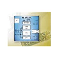
IC CTLR SFP+ ANLG LDD 28-TQFN
Manufacturer
Maxim Integrated Products
Type
Laser Diode Controllerr
Datasheet
1.DS1874TTR.pdf
(88 pages)
Specifications of DS1874T+
Number Of Channels
1
Voltage - Supply
2.85 V ~ 3.9 V
Current - Supply
2.5mA
Operating Temperature
-40°C ~ 95°C
Package / Case
28-WFQFN Exposed Pad
Mounting Type
Surface Mount
Number Of Outputs
5
Duty Cycle (max)
50 %
Output Voltage
0 V to 3.9 V
Mounting Style
SMD/SMT
Switching Frequency
0 KHz to 400 KHz
Operating Supply Voltage
2.85 V to 3.9 V
Supply Current
2.5 mA to 10 mA
Maximum Operating Temperature
+ 95 C
Fall Time
300 ns
Minimum Operating Temperature
- 40 C
Rise Time
300 ns
Synchronous Pin
Yes
Lead Free Status / RoHS Status
Lead free / RoHS Compliant
Other names
90-1874T+000


SFP+ Controller with Digital LDD Interface
Lower Memory, Register 6Eh: STATUS
40
Write Access
______________________________________________________________________________________
6Eh
POWER-ON VALUE
READ ACCESS
WRITE ACCESS
MEMORY TYPE
TXDS
BIT 7
BIT 7
BIT 6
BIT 5
BIT 4
BIT 3
BIT 2
BIT 1
BIT 0
N/A
TXDS: TXD Status Bit. Reflects the logic state of the TXD pin (read only).
0 = TXD pin is logic-low.
1 = TXD pin is logic-high.
TXDC: TXD Software Control Bit. This bit allows for software control that is identical to the TXD pin.
See the section on TXD for further information. Its value is wire-ORed with the logic value of the
TXD pin (writable by all users).
0 = (Default).
1 = Forces the device into a TXD state regardless of the value of the TXD pin.
IN1S: IN1 Status Bit. Reflects the logic state of the IN1 pin (read only).
0 = IN1 pin is logic-low.
1 = IN1 pin is logic-high.
RSELS: RSEL Status Bit. Reflects the logic state of the RSEL pin (read only).
0 = RSEL pin is logic-low.
1 = RSEL pin is logic-high.
RSELC: RSEL Software Control Bit. This bit allows for software control that is identical to the RSEL
pin. Its value is wire-ORed with the logic value of the RSEL pin to create the RSELOUT pin’s logic
value (writable by all users).
0 = (Default).
1 = Forces the device into a RSEL state regardless of the value of the RSEL pin.
TXF: Reflects the driven state of the TXF pin (read only).
0 = TXF pin is driven low.
1 = TXF pin is pulled high.
RXL: Reflects the driven state of the LOSOUT pin (read only).
0 = LOSOUT pin is driven low.
1 = LOSOUT pin is pulled high.
RDYB: Ready Bar.
0 = V
1 = V
TXDC
All
CC
CC
is above POA.
is below POA and/or too low to communicate over the I
X0XX 0XXXb
All
See below
Volatile
IN1S
N/A
RSELS
All
RSELC
All
N/A
TXF
2
C bus.
RXL
N/A
RDYB
BIT 0
N/A
Related parts for DS1874T+
Image
Part Number
Description
Manufacturer
Datasheet
Request
R

Part Number:
Description:
MAX7528KCWPMaxim Integrated Products [CMOS Dual 8-Bit Buffered Multiplying DACs]
Manufacturer:
Maxim Integrated Products
Datasheet:
Part Number:
Description:
Single +5V, fully integrated, 1.25Gbps laser diode driver.
Manufacturer:
Maxim Integrated Products
Datasheet:
Part Number:
Description:
Single +5V, fully integrated, 155Mbps laser diode driver.
Manufacturer:
Maxim Integrated Products
Datasheet:
Part Number:
Description:
VRD11/VRD10, K8 Rev F 2/3/4-Phase PWM Controllers with Integrated Dual MOSFET Drivers
Manufacturer:
Maxim Integrated Products
Datasheet:
Part Number:
Description:
Highly Integrated Level 2 SMBus Battery Chargers
Manufacturer:
Maxim Integrated Products
Datasheet:
Part Number:
Description:
Current Monitor and Accumulator with Integrated Sense Resistor; ; Temperature Range: -40°C to +85°C
Manufacturer:
Maxim Integrated Products
Part Number:
Description:
TSSOP 14/A�/RS-485 Transceivers with Integrated 100O/120O Termination Resis
Manufacturer:
Maxim Integrated Products
Part Number:
Description:
TSSOP 14/A�/RS-485 Transceivers with Integrated 100O/120O Termination Resis
Manufacturer:
Maxim Integrated Products
Part Number:
Description:
QFN 16/A�/AC-DC and DC-DC Peak-Current-Mode Converters with Integrated Step
Manufacturer:
Maxim Integrated Products
Part Number:
Description:
TDFN/A/65V, 1A, 600KHZ, SYNCHRONOUS STEP-DOWN REGULATOR WITH INTEGRATED SWI
Manufacturer:
Maxim Integrated Products
Part Number:
Description:
Integrated Temperature Controller f
Manufacturer:
Maxim Integrated Products
Part Number:
Description:
SOT23-6/I�/45MHz to 650MHz, Integrated IF VCOs with Differential Output
Manufacturer:
Maxim Integrated Products
Part Number:
Description:
SOT23-6/I�/45MHz to 650MHz, Integrated IF VCOs with Differential Output
Manufacturer:
Maxim Integrated Products
Part Number:
Description:
EVALUATION KIT/2.4GHZ TO 2.5GHZ 802.11G/B RF TRANSCEIVER WITH INTEGRATED PA
Manufacturer:
Maxim Integrated Products