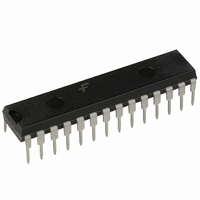
MM74C911N Fairchild Semiconductor, MM74C911N Datasheet - Page 2

MM74C911N
Manufacturer Part Number
MM74C911N
Description
IC CONTROLLER DISPLAY 28-DIP
Manufacturer
Fairchild Semiconductor
Datasheet
1.MM74C911N.pdf
(8 pages)
Specifications of MM74C911N
Display Type
LED
Configuration
7 Segment + DP
Digits Or Characters
4 Digits
Current - Supply
500µA
Voltage - Supply
3 V ~ 6 V
Operating Temperature
-40°C ~ 85°C
Mounting Type
Through Hole
Package / Case
28-DIP (0.600", 15.24mm)
Lead Free Status / RoHS Status
Contains lead / RoHS non-compliant
Interface
-
Lead Free Status / Rohs Status
No
Other names
74C911
74C911N
74C911N
Available stocks
Company
Part Number
Manufacturer
Quantity
Price
Company:
Part Number:
MM74C911N
Manufacturer:
MICROCHIP
Quantity:
1 200
www.fairchildsemi.com
Truth Tables
Functional Description
The MM74C911 display controller is manufactured on stan-
dard metal gate CMOS technology. A single 5V 74 series
TTL supply can be used for power and should be bypassed
at the V
The digit outputs directly drive the base of a grounded
emitter digit transistor without the need of a Darlington con-
figuration. If an MM74C911 is driving a digit transistor and
also supplying digit information to a cascaded MM74C911,
base resistors are needed in the digit transistors to provide
an adequate high level to the digit inputs of the cascaded
MM74C911.
As seen in the Block Diagram, these display controllers
contain four 8-bit registers; any one may be randomly writ-
Logic Diagram
CE
0
0
0
0
0
0
0
0
1
CC
pin to suppress current transients.
K2
X
0
0
0
0
1
1
1
1
Address
Digit
K1
Input Control
0
0
1
1
0
0
1
1
X
WE
X
0
1
0
1
0
1
0
1
Write Digit 1
Latch Digit 1
Write Digit 2
Latch Digit 2
Write Digit 3
Latch Digit 3
Write Digit 4
Latch Digit 4
Disable Writing
Operation
2
R
X
ten into. In normal operation, the internal multiplexer scans
the registers and refreshes the display. In cascaded opera-
tion, 1 MM74C911 serves as a master refresh device and
cascaded MM74C911’s are slaved to it through digit lines
operating as inputs.
The MM74C911 appears to a microprocessor as memory
and to the user as a self-scan display. Since every seg-
ment is under microprocessor control, great versatility is
obtained.
Low power standby operation occurs with both SOE and
DIO inputs HIGH. This condition forces the MM74C911 to a
quiescent state typically drawing less than 1 A of supply
current with a standby supply voltage as low as 3V.
DIO
0
0
1
1
1
1
1
1
Refresh (digit lines sequentially pulsed)
Don’t Care
SOE
0
1
0
0
0
0
0
1
D4 D3 D2 D1
R
R
0
0
0
0
1
0
Digit Lines
R
R
0
0
0
1
0
0
Output Control
R
R
0
0
1
0
0
0
R Refresh Display
R Disable Segment Outputs
0
1
0
0
0
0
Digits Are Now Inputs
Display Digit 1
Display Digit 2
Display Digit 3
Display Digit 4
Power Saver Mode
Operation


