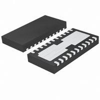
LTC4090EDJC#PBF Linear Technology, LTC4090EDJC#PBF Datasheet - Page 23

LTC4090EDJC#PBF
Manufacturer Part Number
LTC4090EDJC#PBF
Description
IC USB POWER MANAGER 22-DFN
Manufacturer
Linear Technology
Datasheet
1.LTC4090EDJCPBF.pdf
(28 pages)
Specifications of LTC4090EDJC#PBF
Function
Power Management
Battery Type
Lithium-Ion (Li-Ion), Lithium-Polymer (Li-Pol)
Voltage - Supply
4.35 V ~ 5.5 V
Operating Temperature
-40°C ~ 85°C
Mounting Type
Surface Mount
Package / Case
22-WFDFN Exposed Pad
Supply Voltage Range
4.35V To 5.5V
Operating Temperature Range
-40°C To +85°C
Digital Ic Case Style
DFN
No. Of Pins
22
Msl
MSL 1 - Unlimited
Termination Type
SMD
Supply Voltage Min
4.35V
Rohs Compliant
Yes
Filter Terminals
SMD
Frequency
2.7MHz
Lead Free Status / RoHS Status
Lead free / RoHS Compliant
Available stocks
Company
Part Number
Manufacturer
Quantity
Price
APPLICATIONS INFORMATION
designed to work with thermistors whose resistance-tem-
perature characteristics follow Vishay Dale’s R-T curve 2.
The Vishay NTHS0603N02N1002J is an example of such
a thermistor. However, Vishay Dale has many thermistor
products that follow the R-T curve 2 characteristic in a
variety of sizes. Furthermore, any thermistor whose ratio
of r
R-T curve 2 shows a ratio of 2.815/0.409 = 6.89).
In the explanation below, the following notation is used.
R
R
R
r
r
R
R1 = Optional Temperature Range Adjustment resistor
(see Figure 9)
The trip points for the LTC4090/LTC4090-5’s tempera-
ture qualifi cation are internally programmed at 0.29 •
VNTC for the hot threshold and 0.74 • VNTC for the cold
threshold.
COLD
HOT
25C
NTC|COLD
NTC|HOT
NOM
COLD
= Ratio of R
R
10k
= Value of the Thermistor at 25°C
R
10k
VNTC
NOM
= Ratio of R
NTC
= Primary Thermistor Bias Resistor (see Figure 8)
NTC
6
5
to r
= Value of the Thermistor at the Hot Trip Point
= Value of Thermistor at the Cold Trip Point
Figure 8. Typical NTC Thermistor Circuit
HOT
NTC|HOT
0.29 • VNTC
is about 7.0 will also work (Vishay Dale
0.738 • VNTC
NTC|COLD
0.1V
to R
to R
25C
–
+
–
+
+
–
NTC BLOCK
25C
TOO_COLD
TOO_HOT
NTC_ENABLE
4090 F08
Therefore, the hot trip point is set when:
and the cold trip point is set when:
Solving these equations for R
in the following:
and
By setting R
in r
to the Vishay Resistance-Temperature curve 2 chart gives
a hot trip point of about 50°C and a cold trip point of about
0°C. The difference between the hot and cold trip points
is approximately 50°C.
By using a bias resistor, R
R
direction. The temperature span will change somewhat due
to the nonlinear behavior of the thermistor. The following
Figure 9. NTC Thermistor Circuit with Additional Bias Resistor
25C
R
R
R
R
HOT
R
13.2k
R1
1.97k
NTC|HOT
NTC|COLD
NOM
NOM
, the hot and cold trip points can be moved in either
R
10k
NOM
VNTC
NTC
NTC
6
5
= 0.409 and r
R
R
NTC|HOT
NTC|COLD
+ R
+ R
NOM
= 0.409 • R
NTC|HOT
NTC|COLD
= 2.815 • R
0.29 • VNTC
LTC4090/LTC4090-5
equal to R
0.738 • VNTC
COLD
0.1V
• VNTC = 0.29 • VNTC
• VNTC = 0.74 • VNTC
NOM
= 2.815. Referencing these ratios
NOM
25C
NOM
NTC|COLD
–
+
–
+
+
–
NTC BLOCK
, the above equations result
, different in value from
and R
NTC|HOT
TOO_COLD
TOO_HOT
NTC_ENABLE
23
4090 F09
results
4090fc


