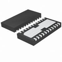
LTC4090EDJC#PBF Linear Technology, LTC4090EDJC#PBF Datasheet - Page 16

LTC4090EDJC#PBF
Manufacturer Part Number
LTC4090EDJC#PBF
Description
IC USB POWER MANAGER 22-DFN
Manufacturer
Linear Technology
Datasheet
1.LTC4090EDJCPBF.pdf
(28 pages)
Specifications of LTC4090EDJC#PBF
Function
Power Management
Battery Type
Lithium-Ion (Li-Ion), Lithium-Polymer (Li-Pol)
Voltage - Supply
4.35 V ~ 5.5 V
Operating Temperature
-40°C ~ 85°C
Mounting Type
Surface Mount
Package / Case
22-WFDFN Exposed Pad
Supply Voltage Range
4.35V To 5.5V
Operating Temperature Range
-40°C To +85°C
Digital Ic Case Style
DFN
No. Of Pins
22
Msl
MSL 1 - Unlimited
Termination Type
SMD
Supply Voltage Min
4.35V
Rohs Compliant
Yes
Filter Terminals
SMD
Frequency
2.7MHz
Lead Free Status / RoHS Status
Lead free / RoHS Compliant
Available stocks
Company
Part Number
Manufacturer
Quantity
Price
LTC4090/LTC4090-5
OPERATION
where V
total resistance from the PROG pin to ground. Keep in
mind that when the LTC4090/LTC4090-5 are powered
from the IN pin, the programmed input current limit takes
precedence over the charge current. In such a scenario,
the charge current cannot exceed the programmed input
current limit.
For example, if typical 500mA charge current is required,
calculate:
For best stability over temperature and time, 1% metal
fi lm resistors are recommended. Under trickle charge
conditions, this current is reduced to 10% of the full-
scale value.
The Charge Timer
The programmable charge timer is used to terminate the
charge cycle. The timer duration is programmed by an
external capacitor at the TIMER pin. The charge time is
typically:
The timer starts when an input voltage greater than the
undervoltage lockout threshold level is applied or when
leaving shutdown and the voltage on the battery is less than
the recharge threshold. At power-up or exiting shutdown
with the battery voltage less than the recharge threshold,
the charge time is a full cycle. If the battery is greater than
the recharge threshold the timer will not start and charging
is prevented. If after power-up the battery voltage drops
below the recharge threshold, or if after a charge cycle
the battery voltage is still below the recharge threshold,
the charge time is set to one-half of a full cycle.
The LTC4090/LTC4090-5 have a feature that extends charge
time automatically. Charge time is extended if the charge
current in constant-current mode is reduced due to load
current or thermal regulation. This change in charge time
is inversely proportional to the change in charge current.
16
R
t
TIMER
PROG
PROG
(hours) =
=
500mA
is the PROG pin voltage and R
1V
C
• 50,000 = 100k
TIMER
0.1µF • 100k
• R
PROG
• 3hours
PROG
is the
As the LTC4090/LTC4090-5 approach constant-voltage
mode the charge current begins to drop. This change in
charge current is due to normal charging operation and
does not affect the timer duration.
Consider, for example, a USB charge condition where
R
corresponds to a three hour charge cycle. However, if the
HPWR input is set to a logic low, then the input current
limit will be reduced from 500mA to 100mA. With no ad-
ditional system load, this means the charge current will
be reduced to 100mA. Therefore, the termination timer
will automatically slow down by a factor of fi ve until the
charger reaches constant-voltage mode (i.e., V
proaches 4.2V) or HPWR is returned to a logic high. The
charge cycle is automatically lengthened to account for
the reduced charge current. The exact time of the charge
cycle will depend on how long the charger remains in
constant-current mode and/or how long the HPWR pin
remains logic low.
Once a timeout occurs and the voltage on the battery is
greater than the recharge threshold, the charge current
stops, and the CHRG output assumes a high impedance
state if it has not already done so.
Connecting the TIMER pin to ground disables the battery
charger.
CHRG Status Output Pin
When the charge cycle starts, the CHRG pin is pulled to
ground by an internal N-channel MOSFET capable of driv-
ing an LED. When the charge current drops below 10%
of the programmed full charge current while in constant-
voltage mode, the pin assumes a high impedance state,
but charge current continues to fl ow until the charge
time elapses. If this state is not reached before the end
of the programmable charge time, the pin will assume a
high impedance state when a timeout occurs. The CHRG
current detection threshold can be calculated by the fol-
lowing equation:
CLPROG
I
DETECT
= 2k, R
=
R
0.1V
PROG
PROG
• 50,000 =
= 100k and C
5000V
R
PROG
TIMER
= 0.1μF . This
BAT
4090fc
ap-


