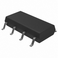
FSDM311L Fairchild Semiconductor, FSDM311L Datasheet - Page 8

FSDM311L
Manufacturer Part Number
FSDM311L
Description
IC SWIT PWM GREEN OVP HV 8SOP
Manufacturer
Fairchild Semiconductor
Datasheet
1.FSDM311L.pdf
(19 pages)
Specifications of FSDM311L
Output Isolation
Isolated
Frequency Range
61 ~ 73kHz
Voltage - Input
7 ~ 20 V
Voltage - Output
650V
Power (watts)
13W
Operating Temperature
25°C ~ 150°C
Package / Case
8-SOP, 8-LSOP
Lead Free Status / RoHS Status
Lead free / RoHS Compliant
Other names
FSDM311L_NL
FSDM311L_NL
FSDM311L_NL
Available stocks
Company
Part Number
Manufacturer
Quantity
Price
Company:
Part Number:
FSDM311L
Manufacturer:
FAIRCHIL
Quantity:
20 000
© 2003 Fairchild Semiconductor Corporation
FSDM311 Rev. 1.1.0 • 7/14/06
Functional Description
1. Start-up: At start-up, the internal high-voltage current
source supplies the internal bias and charges the
external Vcc capacitor, as shown in Figure 15. In the
case of the FSDM311, when Vcc reaches 9V, the device
starts switching and the internal high-voltage current
source stops charging the capacitor. The device is in
normal operation provided that Vcc does not drop below
7V. After start-up, the bias is supplied from the auxiliary
transformer winding.
Calculating the Vcc capacitor is an important step in
design with the FSDM311. At initial start-up in the
FSDM311, the maximum value of start operating current
I
and Vref Blocks. The charging current I
capacitor is equal to I
UVLO start voltage, only the bias winding supplies Vcc
current to the device. When the bias winding voltage is
not sufficient, the Vcc level decreases to the UVLO stop
voltage and the internal current source is activated
again to charge the Vcc capacitor. To prevent this Vcc
fluctuation (charging/discharging), a Vcc with a value
between 10uF and 47μF should be chosen.
START
is about 100μA, which supplies current to UVLO
Figure 15. Internal Startup Circuit
STR
- I
START
. After V
CC
Vcc
reaches the
of the Vcc
8
2. Feedback Control: The FSDM311 is a voltage-mode
controlled device, as shown in Figure 17. Usually, an
opto-coupler with shunt regulator, like KA431, is used to
implement the feedback network. The feedback voltage
is compared with an internally generated sawtooth
waveform, which directly controls the duty cycle. When
the KA431 reference pin voltage exceeds the internal
reference voltage of 2.5V, the opto-coupler LED current
increases, the feedback voltage Vfb is pulled down, and
it reduces the duty cycle. This happens when the input
voltage increases or the output load decreases.
Figure 16. Charging Vcc Capacitor Through Vstr
Figure 17. PWM and Feedback Circuit
www.fairchildsemi.com


