100325QC Fairchild Semiconductor, 100325QC Datasheet - Page 5
100325QC
Manufacturer Part Number
100325QC
Description
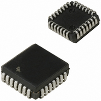
IC TRANSLATR HEX ECL/TTL 28-PLCC
Manufacturer
Fairchild Semiconductor
Datasheet
1.100325QC.pdf
(9 pages)
Specifications of 100325QC
Logic Function
Translator
Number Of Bits
6
Input Type
ECL
Output Type
TTL
Number Of Channels
6
Number Of Outputs/channel
1
Differential - Input:output
Yes/No
Propagation Delay (max)
3.5ns
Voltage - Supply
4.5 V ~ 5.5 V
Operating Temperature
-40°C ~ 85°C
Package / Case
28-PLCC
Supply Voltage
4.5 V ~ 5.5 V
Logic Family
ECL
Logical Function
Translator
Technology
ECL
High Level Output Current
-2mA
Low Level Output Current
20mA
Translation
ECL to TTL
Operating Supply Voltage (typ)
±5V
Package Type
PLCC
Operating Supply Voltage (max)
-5.7/5.5V
Operating Supply Voltage (min)
-4.2/4.5V
Abs. Propagation Delay Time
4.6ns
Mounting
Surface Mount
Pin Count
28
Operating Temperature (min)
0C
Operating Temperature (max)
85C
Operating Temperature Classification
Commercial
Lead Free Status / RoHS Status
Lead free / RoHS Compliant
Data Rate
-
Lead Free Status / Rohs Status
Compliant
Available stocks
Company
Part Number
Manufacturer
Quantity
Price
Company:

Part Number:
100325QC
Manufacturer:
Fairchild Semiconductor
Quantity:
10 000
Part Number:
100325QC
Manufacturer:
NS/国半
Quantity:
20 000
Company:
Part Number:
100325QCX
Manufacturer:
Fairchild Semiconductor
Quantity:
10 000
Part Number:
100325QCX
Manufacturer:
FAIRCHILD/仙童
Quantity:
20 000


V
V
V
V
V
V
V
I
I
I
I
I
t
t
t
t
IH
IL
OS
EE
TTL
PLH
PHL
PLH
PHL
Industrial Version
PLCC DC Electrical Characteristics
V
Note 6: The specified limits represent the “worst case” value for the parameter. Since these values normally occur at the temperature extremes, additional
noise immunity and guardbanding can be achieved by decreasing the allowable system operating ranges. Conditions for testing shown in the tables are cho-
sen to guarantee operation under “worst case” conditions.
Note 7: Test one output at a time.
PLCC AC Electrical Characteristics
V
Switching Waveform
BB
IH
IL
OH
OL
DIFF
CM
Symbol
Symbol
EE
EE
4.2V to 5.7V, V
4.2V to 5.7V, V
Output Reference Voltage
Single-Ended Input
HIGH Voltage
Single-Ended Input
LOW Voltage
Output HIGH Voltage
Output LOW Voltage
Input Voltage Differential
Common Mode Voltage
Input HIGH Current
Input LOW Current
Output Short-Circuit Current
V
V
Propagation Delay
Data to Output
Propagation Delay
Data to Output
EE
TTL
Power Supply Current
Power Supply Current
Parameter
Parameter
CC
CC
GND, T
GND, V
C
TTL
0.80
1.60
Min
V
T
CC
40 C to 85 C (Note 6)
C
Min
1395
1830
150
1170
2.5
0.5
150
4.5V to 5.5V
37
T
C
2.0 V
FIGURE 1. Propagation Delay
40 C
Max
3.30
4.10
40 C
CC
Max
1255
1480
450
0.5
870
65
60
15
0.5 V
0.90
1.70
Min
T
T
CC
C
C
5
Min
1380
1165
1830
150
2.5
0.5
150
37
0 C to 85 C
2.0 V
25 C
Max
3.50
4.30
CC
Max
1260
1475
350
0.5
870
65
60
17
0.5
1.00
1.80
Min
T
Units
C
mV
mV
mV
mV
mA
mA
mA
V
V
V
A
A
85 C
Max
3.80
4.60
I
Guaranteed HIGH Signal for All Inputs
(with One Input Tied to V
Guaranteed LOW Signal for All Inputs
(with One Input Tied to V
I
I
Required for Full Output Swing
V
D
V
V
D
D
VBB
OH
OL
IN
IN
OUT
0
0
0
–D
–D
–D
20 mA
5
5
5
V
V
2.0 mA
IH (Max)
IL (Min)
GND (Note 7)
2.1 mA
V
V
V
Units
IL (Min)
BB
BB
ns
ns
, D
, D
Conditions
0
0
www.fairchildsemi.com
–D
–D
C
Figures 1, 2
C
Figures 1, 3
5
L
L
5
V
15 pF
50 pF
V
or V
V
BB
BB
Conditions
BB
IN
BB
)
)
,
IL (Min)
V
IH (Max)
Related parts for 100325QC
Image
Part Number
Description
Manufacturer
Datasheet
Request
R

Part Number:
Description:
Fairchild Semiconductor [IGBT MODULE]
Manufacturer:
Fairchild Semiconductor
Datasheet:

Part Number:
Description:
Discrete Semiconductor Modules
Manufacturer:
Fairchild Semiconductor
Part Number:
Description:
Discrete Semiconductor Modules
Manufacturer:
Fairchild Semiconductor
Part Number:
Description:
This N-Channel MOSFET is produced using Fairchild Semiconductor’s advanced Power Trench® process
Manufacturer:
Fairchild Semiconductor
Datasheet:
Part Number:
Description:
This N-Channel MOSFET is produced using Fairchild Semiconductor’s advanced Power Trench® process
Manufacturer:
Fairchild Semiconductor
Datasheet:
Part Number:
Description:
This N-Channel MOSFET is produced using Fairchild Semiconductor’s advanced PowerTrench® process
Manufacturer:
Fairchild Semiconductor
Datasheet:
Part Number:
Description:
This N-Channel MOSFET is produced using Fairchild Semiconductor’s advanced PowerTrench® process
Manufacturer:
Fairchild Semiconductor
Datasheet:
Part Number:
Description:
This N-Channel MOSFET is produced using Fairchild Semiconductor’s advanced Power Trench® process
Manufacturer:
Fairchild Semiconductor
Datasheet:
Part Number:
Description:
This N-Channel logic Level MOSFETs are produced using Fairchild Semiconductor‘s advanced Power Trench® process that has been special tailored to minimize the on-state resistance and yet maintain superior switching performance
Manufacturer:
Fairchild Semiconductor
Datasheet:
Part Number:
Description:
This N-Channel MOSFET is produced using Fairchild Semiconductor’s advanced Power Trench® process
Manufacturer:
Fairchild Semiconductor
Datasheet:
Part Number:
Description:
This N-Channel SyncFET™ is produced using Fairchild Semiconductor’s advanced PowerTrench® process
Manufacturer:
Fairchild Semiconductor
Datasheet:
Part Number:
Description:
This N-Channel SyncFET™ is produced using Fairchild Semiconductor’s advanced PowerTrench® process
Manufacturer:
Fairchild Semiconductor
Datasheet:
Part Number:
Description:
This N-Channel SyncFET™ is produced using Fairchild Semiconductor’s advanced PowerTrench® process
Manufacturer:
Fairchild Semiconductor
Datasheet:
Part Number:
Description:
This N-Channel logic Level MOSFETs are produced using Fairchild Semiconductor‘s advanced Power Trench® process that has been special tailored to minimize the on-state resistance and yet maintain superior switching performance
Manufacturer:
Fairchild Semiconductor
Datasheet:
Part Number:
Description:
This N-Channel MOSFET is produced using Fairchild Semiconductor’s advanced Power Trench® process that has been especially tailored to minimize the on-state resistance and yet maintain superior switching performance
Manufacturer:
Fairchild Semiconductor
Datasheet: