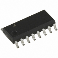
74VHC123AM Fairchild Semiconductor, 74VHC123AM Datasheet - Page 3

74VHC123AM
Manufacturer Part Number
74VHC123AM
Description
IC MULTIVIBRATOR MONO DL 16-SOIC
Manufacturer
Fairchild Semiconductor
Series
74VHCr
Specifications of 74VHC123AM
Logic Type
Monostable
Independent Circuits
2
Schmitt Trigger Input
No
Propagation Delay
8.1ns
Current - Output High, Low
8mA, 8mA
Voltage - Supply
2 V ~ 5.5 V
Operating Temperature
-40°C ~ 85°C
Mounting Type
Surface Mount
Package / Case
16-SOIC (3.9mm Width)
Elements Per Chip
2
Logic Family
VHC
Input Bias Current (max)
0.004 mA
Propagation Delay Time
24.1 ns, 14 ns
High Level Output Current
- 8 mA
Low Level Output Current
8 mA
Supply Voltage (max)
5.5 V
Supply Voltage (min)
2 V
Maximum Operating Temperature
+ 85 C
Minimum Operating Temperature
- 40 C
Mounting Style
SMD/SMT
Operating Supply Voltage
2.5 V, 3.3 V, 5 V
Multivibrator Type
Dual Retriggerable Monostable
Output Current
8mA
Logic Case Style
SOIC
No. Of Pins
16
Supply Voltage Range
2V To 5.5V
Rohs Compliant
Yes
Dc
0052
Lead Free Status / RoHS Status
Lead free / RoHS Compliant
Available stocks
Company
Part Number
Manufacturer
Quantity
Price
Part Number:
74VHC123AM
Manufacturer:
FSC
Quantity:
20 000
Company:
Part Number:
74VHC123AMTCX
Manufacturer:
FAIRCHILD
Quantity:
500
Company:
Part Number:
74VHC123AMTCX
Manufacturer:
FAIRCHILD
Quantity:
2 316
Part Number:
74VHC123AMTCX
Manufacturer:
FAIRCHILD/仙童
Quantity:
20 000
Company:
Part Number:
74VHC123AMTCX VHC123
Manufacturer:
TriQuint
Quantity:
100
Company:
Part Number:
74VHC123AMTCX(V123A)
Manufacturer:
FCS
Quantity:
169
Company:
Part Number:
74VHC123AMX
Manufacturer:
FAI
Quantity:
69
Part Number:
74VHC123AMX
Manufacturer:
FAIRCHILD/仙童
Quantity:
20 000
Timing Chart
Functional Description
1. Stand-by State
2. Trigger Operation
The external capacitor (C
the Stand-by State. That means, before triggering, the
Q
C
relate to the timing of the output pulse, and two refer-
ence voltage supplies turn off. The total supply current
is only leakage current.
Trigger operation is effective in any of the following
three cases. First, the condition where the A input is
LOW, and B input has a rising signal; second, where
the B input is HIGH, and the A input has a falling signal;
and third, where the A input is LOW and the B input is
HIGH, and the CLR input has a rising signal.
After a trigger becomes effective, comparators C
C
capacitor discharges through Q
the R
the internal reference voltage V
becomes LOW. The flip-flop is then reset and Q
off. At that moment C
ing.
After Q
rising at a rate determined by the time constant of
external capacitor C
Upon triggering, output Q becomes HIGH, following
some delay time of the internal F/F and gates. It stays
HIGH even if the voltage of R
to rising. When R
P
x
2
start operating, and Q
and Q
node are in the off state. Two comparators that
x
/C
N
x
turns off, the voltage at the R
N
node drops. If the R
transistors which are connected to the R
x
/C
x
and resistor R
x
1
reaches the internal reference
stops but C
N
x
) is fully charged to V
is turned on. The external
x
x
/C
/C
N
ref
x
. The voltage level at
x
changes from falling
voltage level falls to
L, the output of C
2
x
.
continues operat-
x
/C
x
node starts
N
1
CC
turns
and
in
x
1
/
3
3. Retrigger operation (74VHC123A)
4. Reset Operation
voltage V
put Q goes LOW and C
means, after triggering, when the voltage level of the
R
MONOSTABLE state.
With large values of C
charge time of the capacitor and internal delays of the
IC, the width of the output pulse, t
lows:
t
When a new trigger is applied to either input A or B
while in the MONOSTABLE state, it is effective only if
the IC is charging C
node then falls to V
output stays HIGH if the next trigger comes in before
the time period set by C
If the new trigger is very close to a previous trigger,
such as an occurrence during the discharge cycle, it
will have no effect.
The minimum time for a trigger to be effective 2nd trig-
ger, t
In normal operation, the CLR input is held HIGH. If
CLR is LOW, a trigger has no affect because the Q out-
put is held LOW and the trigger control F/F is reset.
Also, Q
This means if CLR is set LOW, the IC goes into a wait
state.
W
x
/C
(OUT)
x
RR
node reaches V
p
(Min), depends on V
turns on and C
ref
H, the output of C
1.0 C
x
R
x
ref
x
. The voltage level of the R
L level again. Therefore the Q
x
x
x
and R
and R
is charged rapidly to V
ref
2
H, the IC returns to its
CC
stops its operation. That
2
becomes LOW, the out-
x
x
and C
, and ignoring the dis-
.
W
www.fairchildsemi.com
x
(OUT), is as fol-
.
CC
.
x
/C
x


