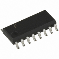
74VHC221AM Fairchild Semiconductor, 74VHC221AM Datasheet - Page 7

74VHC221AM
Manufacturer Part Number
74VHC221AM
Description
MULTIVIBRATOR DUAL MONO 16SOIC
Manufacturer
Fairchild Semiconductor
Series
74VHCr
Datasheet
1.74VHC221AMTCX.pdf
(12 pages)
Specifications of 74VHC221AM
Logic Type
Monostable
Independent Circuits
2
Schmitt Trigger Input
No
Propagation Delay
8.1ns
Current - Output High, Low
8mA, 8mA
Voltage - Supply
2 V ~ 5.5 V
Operating Temperature
-40°C ~ 85°C
Mounting Type
Surface Mount
Package / Case
16-SOIC (3.9mm Width)
Elements Per Chip
2
Logic Family
VHC
Input Bias Current (max)
0.004 mA
Propagation Delay Time
24.1 ns, 14 ns
High Level Output Current
- 8 mA
Low Level Output Current
8 mA
Supply Voltage (max)
5.5 V
Supply Voltage (min)
2 V
Maximum Operating Temperature
+ 85 C
Minimum Operating Temperature
- 40 C
Mounting Style
SMD/SMT
Operating Supply Voltage
2.5 V, 3.3 V, 5 V
Lead Free Status / RoHS Status
Lead free / RoHS Compliant
Available stocks
Company
Part Number
Manufacturer
Quantity
Price
Company:
Part Number:
74VHC221AM
Manufacturer:
Fairchild Semiconductor
Quantity:
1 816
Company:
Part Number:
74VHC221AMTCX
Manufacturer:
ABOV
Quantity:
26
Company:
Part Number:
74VHC221AMTCX
Manufacturer:
FSC
Quantity:
8 300
©1994 Fairchild Semiconductor Corporation
74VHC221A Rev. 1.2
AC Electrical Characteristics
Notes:
4. Refer to 74VHC221A Timing Chart.
5. C
AC Operating Requirement
t
t
t
Symbol
PLH
PLH
PLH
I
I
Duty: %
t
Symbol
consumption without load. Average operating current can be obtained by the equation:
WOUT
CC
CC
t
C
C
wOUT
t
PD
t
t
, t
, t
, t
PD
W
W
W
IN
1
(opr.)
PHL
PHL
PHL
: Active Supply Current
(H)
(L)
(L)
is defined as the value of the internal equivalent capacitance which is calculated from the operating current
Propagation Delay Time
(A, B–Q, Q)
Propagation Delay Time
(CLR Trigger—Q, Q)
Propagation Delay Time
(CLR—Q, Q)
Output Pulse Width
Output Pulse Width Error
Between Circuits
(In same Package)
Input Capacitance
Power Dissipation
Capacitance
C
Minimum Trigger
Pulse Width
Minimum Clear Pulse Width
PD
Parameter
• V
CC
Parameter
• f
IN +
I
CC
1
• Duty / 100 + I
3.3 ± 0.3 C
5.0 ± 0.5 C
3.3 ± 0.3 C
5.0 ± 0.5 C
3.3 ± 0.3 C
5.0 ± 0.5 C
3.3 ± 0.3
5.0 ± 0.5
3.3 ± 0.3 C
5.0 ± 0.5
3.3 ± 0.3 C
5.0 ± 0.5
3.3 ± 0.3 C
5.0 ± 0.5
V
CC
2.0
(4)
(V)
V
CC
C
C
C
C
C
C
C
R
Rx
Cx
Rx
Rx
V
(5)
3.3
5.0
3.3
5.0
CC
L
L
L
L
L
L
L
L
L
L
L
L
X
X
L
L
L
CC
(V)
Conditions
15pF
50pF
15pF
50pF
15pF
50pF
15pF
50pF
15pF
50pF
15pF
50pF
50pF, Cx
50pF,
50pF, Cx
2k
0.01µF,
10k
10k
28pF, C
6k
/ 2 (per Circuit)
Open
Min.
7
5.0
5.0
5.0
5.0
L
0.1µF,
50pF,
28pF,
T
A
Typ.
25°C
Min.
0.9
0.9
90
90
Max.
T
A
Typ.
13.4
15.9
14.5
17.0
10.2
10.3
12.8
415
345
312
160
133
100
100
8.1
9.6
8.7
6.3
7.8
1.0
1.0
±1
73
4
25°C
T
A
Min.
5.0
5.0
5.0
Max.
5.0
20.6
24.1
12.0
14.0
22.4
25.9
12.9
14.9
15.8
19.3
11.4
240
200
110
110
9.4
1.1
1.1
10
–40°C to +85°C
Min.
T
1.0
1.0
1.0
1.0
1.0
1.0
1.0
1.0
1.0
1.0
1.0
1.0
0.9
0.9
90
90
to +85°C
A
Max.
–40°C
Max.
www.fairchildsemi.com
24.0
27.5
14.0
16.0
26.0
29.5
15.0
17.0
18.5
22.0
11.0
13.0
300
240
110
110
1.1
1.1
10
Units
Units
ns
ns
ms
pF
pF
ns
ns
ns
ns
ns
ns
ns
ns
µs
%


