DM7474N Fairchild Semiconductor, DM7474N Datasheet - Page 2
DM7474N
Manufacturer Part Number
DM7474N
Description
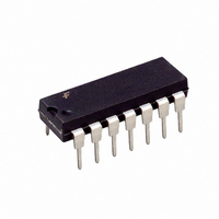
IC FLIP FLOP DUAL D-TYPE 14-DIP
Manufacturer
Fairchild Semiconductor
Series
7400r
Type
D-Typer
Datasheet
1.DM7474N.pdf
(5 pages)
Specifications of DM7474N
Function
Set(Preset) and Reset
Output Type
Differential
Number Of Elements
2
Number Of Bits Per Element
1
Frequency - Clock
15MHz
Delay Time - Propagation
25ns
Trigger Type
Positive Edge
Current - Output High, Low
400µA, 16mA
Voltage - Supply
4.75 V ~ 5.25 V
Operating Temperature
0°C ~ 70°C
Mounting Type
Through Hole
Package / Case
14-DIP (0.300", 7.62mm)
Lead Free Status / RoHS Status
Contains lead / RoHS non-compliant
Other names
7474
7474N
7474N
Available stocks
Company
Part Number
Manufacturer
Quantity
Price

Part Number:
DM7474N
Manufacturer:
NS/国半
Quantity:
20 000


www.fairchildsemi.com
V
V
V
I
I
I
I
I
V
V
V
I
I
f
t
t
t
T
Absolute Maximum Ratings
Recommended Operating Conditions
Note 3: The symbol ( ) indicates the rising edge of the clock pulse is used for reference.
Note 4: T
Electrical Characteristics
over recommended operating free air temperature range (unless otherwise noted)
I
IH
IL
OS
CC
Note 5: All typicals are at V
Note 6: Not more than one output should be shorted at a time.
Note 7: With all outputs open, I
Note 8: Clear is tested with preset HIGH and preset is tested with clear HIGH.
Supply Voltage
Input Voltage
Operating Free Air Temperature Range
Storage Temperature Range
OH
OL
CLK
W
SU
H
I
OH
OL
A
Symbol
CC
IH
IL
Symbol
A
25 C and V
Input Clamp Voltage
HIGH Level
Output Voltage
LOW Level
Output Voltage
Input Current @ Max Input Voltage
HIGH Level
Input Current
LOW Level
Input Current
Short Circuit Output Current
Supply Current
Supply Voltage
HIGH Level Input Voltage
LOW Level Input Voltage
HIGH Level Output Current
LOW Level Output Current
Clock Frequency (Note 4)
Pulse Width
(Note 4)
Input Setup Time (Note 3)(Note 4)
Input Hold Time (Note 3)(Note 4)
Free Air Operating Temperature
CC
Parameter
CC
5V.
CC
5V, T
is measured with the Q and Q outputs HIGH in turn. At the time of measurement the clock is grounded.
Parameter
A
25 C.
Clock HIGH
Clock LOW
Clear LOW
Preset LOW
V
V
V
V
V
V
V
V
V
V
(Note 8)
V
V
CC
CC
IL
CC
IH
CC
CC
I
CC
I
CC
CC
65 C to 150 C
(Note 2)
2.4V
0.4V
0 C to 70 C
Max, V
Min, V
Min, I
Min, I
Min, I
Max, V
Max
Max
Max (Note 6)
Max (Note 7)
I
OH
OL
IL
IH
I
5.5V
Max
12 mA
5.5V
Min
7V
Max
Max
Conditions
4.75
Min
20
2
30
37
30
30
5
2
0
0
Note 2: The “Absolute Maximum Ratings” are those values beyond which
the safety of the device cannot be guaranteed. The device should not be
operated at these limits. The parametric values defined in the Electrical
Characteristics tables are not guaranteed at the absolute maximum ratings.
The “Recommended Operating Conditions” table will define the conditions
for actual device operation.
D
Clock
Clear
Preset
D
Clock
Clear
Preset
Nom
5
Min
2.4
18
(Note 5)
Max
5.25
0.8
16
15
70
0.4
Typ
3.4
0.2
17
Max
120
0.4
40
80
40
30
1.5
1.6
3.2
3.2
1.6
1
55
Units
MHz
mA
mA
ns
ns
ns
V
V
V
C
Units
mA
mA
mA
mA
V
V
V
A
Related parts for DM7474N
Image
Part Number
Description
Manufacturer
Datasheet
Request
R

Part Number:
Description:
Fairchild Semiconductor [IGBT MODULE]
Manufacturer:
Fairchild Semiconductor
Datasheet:

Part Number:
Description:
Discrete Semiconductor Modules
Manufacturer:
Fairchild Semiconductor
Part Number:
Description:
Discrete Semiconductor Modules
Manufacturer:
Fairchild Semiconductor
Part Number:
Description:
This N-Channel MOSFET is produced using Fairchild Semiconductor’s advanced Power Trench® process
Manufacturer:
Fairchild Semiconductor
Datasheet:
Part Number:
Description:
This N-Channel MOSFET is produced using Fairchild Semiconductor’s advanced Power Trench® process
Manufacturer:
Fairchild Semiconductor
Datasheet:
Part Number:
Description:
This N-Channel MOSFET is produced using Fairchild Semiconductor’s advanced PowerTrench® process
Manufacturer:
Fairchild Semiconductor
Datasheet:
Part Number:
Description:
This N-Channel MOSFET is produced using Fairchild Semiconductor’s advanced PowerTrench® process
Manufacturer:
Fairchild Semiconductor
Datasheet:
Part Number:
Description:
This N-Channel MOSFET is produced using Fairchild Semiconductor’s advanced Power Trench® process
Manufacturer:
Fairchild Semiconductor
Datasheet:
Part Number:
Description:
This N-Channel logic Level MOSFETs are produced using Fairchild Semiconductor‘s advanced Power Trench® process that has been special tailored to minimize the on-state resistance and yet maintain superior switching performance
Manufacturer:
Fairchild Semiconductor
Datasheet:
Part Number:
Description:
This N-Channel MOSFET is produced using Fairchild Semiconductor’s advanced Power Trench® process
Manufacturer:
Fairchild Semiconductor
Datasheet:
Part Number:
Description:
This N-Channel SyncFET™ is produced using Fairchild Semiconductor’s advanced PowerTrench® process
Manufacturer:
Fairchild Semiconductor
Datasheet:
Part Number:
Description:
This N-Channel SyncFET™ is produced using Fairchild Semiconductor’s advanced PowerTrench® process
Manufacturer:
Fairchild Semiconductor
Datasheet:
Part Number:
Description:
This N-Channel SyncFET™ is produced using Fairchild Semiconductor’s advanced PowerTrench® process
Manufacturer:
Fairchild Semiconductor
Datasheet:
Part Number:
Description:
This N-Channel logic Level MOSFETs are produced using Fairchild Semiconductor‘s advanced Power Trench® process that has been special tailored to minimize the on-state resistance and yet maintain superior switching performance
Manufacturer:
Fairchild Semiconductor
Datasheet:
Part Number:
Description:
This N-Channel MOSFET is produced using Fairchild Semiconductor’s advanced Power Trench® process that has been especially tailored to minimize the on-state resistance and yet maintain superior switching performance
Manufacturer:
Fairchild Semiconductor
Datasheet: