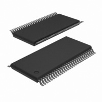
SC28L202A1DGG/G:11 NXP Semiconductors, SC28L202A1DGG/G:11 Datasheet - Page 53

SC28L202A1DGG/G:11
Manufacturer Part Number
SC28L202A1DGG/G:11
Description
IC UART DUAL W/FIFO 56-TSSOP
Manufacturer
NXP Semiconductors
Series
IMPACTr
Datasheet
1.SC28L202A1DGG118.pdf
(77 pages)
Specifications of SC28L202A1DGG/G:11
Features
False-start Bit Detection
Number Of Channels
2, DUART
Fifo's
256 Byte
Voltage - Supply
3.3V, 5V
With Parallel Port
Yes
With Auto Flow Control
Yes
With False Start Bit Detection
Yes
With Modem Control
Yes
With Cmos
Yes
Mounting Type
Surface Mount
Package / Case
56-TFSOP (0.240", 6.10mm Width)
Lead Free Status / RoHS Status
Lead free / RoHS Compliant
Other names
935279792112
SC28L202A1DGG/G
SC28L202A1DGG/G
SC28L202A1DGG/G
SC28L202A1DGG/G
Philips Semiconductors
ISR – Interrupt Status Register
This register provides the status of all potential interrupt sources. The contents of this register are masked by the Interrupt Mask Register (IMR).
If a bit in the ISR is a ‘1’ and the corresponding bit in the IMR is also a ‘1’ then INTRN output will be asserted (Low). If the corresponding bit in
the IMR is a zero the state of the bit in the ISR has no effect on the INTRN output. Note that the IMR does not mask the reading of the ISR – the
true status will be provided regardless of the contents of the IMR. The contents of this register are initialized to H‘00’ when the DUART is reset.
ISR[7] – Input Port Change Status
This bit is a ‘1’ when a change–of–state has occurred at the
I/O(3:0)A or B inputs and that event has been selected to cause an
interrupt by the programming of ACR[3:0]. The bit is cleared when
the CPU reads the IPCR.
ISR[6] – Channel B Change In Break
This bit, when set, indicates that the Channel B receiver has
detected the beginning or the end of a received break. It is reset
when the CPU issues a Channel B ‘reset break change interrupt’
command.
ISR[5] – Rx B Interrupt
This bit indicates that the channel B receiver is interrupting
according to the fill level programmed by the MR0 and MR1
registers. This bit has a different meaning than the receiver
ready/full bit in the status register.
ISR[4] – Tx B Interrupt
This bit indicates that the channel B transmitter is interrupting
according to the interrupt level programmed in the MR0[5:4] bits.
This bit has a different meaning than the Tx RDY bit in the status
register.
ISR[3] – Counter Ready.
In the counter mode, this bit is set when the counter reaches
terminal count and is reset when the counter is stopped by a stop
counter command.
2005 Nov 01
ISR
Dual UART
Bit 7
INPUT
PORT
CHANGE
0=not enabled
1=enabled
BIT 6
DELTA
Break B
0=not enabled
1=enabled
BIT 5
RxRDY/
FFULL B
0=not enabled
1=enabled
BIT 4
TxRDY B
0=not enabled
1=enabled
47
In the timer mode, this bit is set once each cycle of the generated
square wave (every other time that the counter/timer reaches zero
count). The bit is reset by a stop counter command. The command,
however, does not stop the counter/timer.
ISR[2] – Channel A Change in Break
This bit, when set, indicates that the Channel A receiver has
detected the beginning or the end of a received break. It is reset
when the CPU issues a Channel A ‘reset break change interrupt’
command.
ISR[1] – Rx A Interrupt
This bit indicates that the channel A receiver is interrupting
according to the fill level programmed by the MR0 and MR1
registers. This bit has a different meaning than the receiver
ready/full bit in the status register.
ISR[0] – Tx A Interrupt
This bit indicates that the channel A transmitter is interrupting
according to the interrupt level programmed in the MR0[5:4] bits.
This bit has a different meaning than the Tx RDY bit in the status
register.
BIT 3
Counter
Ready
0=not enabled
1=enabled
BIT 2
Delta
Break A
0=not enabled
1=enabled
BIT 1
RxRDY/
FFULL A
0=not enabled
1=enabled
SC28L202
Product data sheet
BIT 0
TxRDY A
0=not enabled
1=enabled


