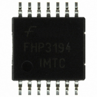
FHP3194IMTC14X Fairchild Semiconductor, FHP3194IMTC14X Datasheet - Page 13

FHP3194IMTC14X
Manufacturer Part Number
FHP3194IMTC14X
Description
MUX 4:1 ANALOG HI SPEED 14-TSSOP
Manufacturer
Fairchild Semiconductor
Datasheet
1.FHP3194IM14X.pdf
(17 pages)
Specifications of FHP3194IMTC14X
Function
Multiplexer
Circuit
1 x 4:1
Voltage Supply Source
Single Supply
Voltage - Supply, Single/dual (±)
5 V ~ 12 V
Operating Temperature
-40°C ~ 85°C
Mounting Type
Surface Mount
Package / Case
14-TSSOP
Lead Free Status / RoHS Status
Lead free / RoHS Compliant
Other names
FHP3194IMTC14XTR
© 2006 Fairchild Semiconductor Corporation
FHP3194 Rev. 1.0.1
Overdrive Recovery
For an amplifier, an overdrive condition occurs when the
output and/or input ranges are exceeded. The recovery
time varies based on whether the input or output is
overdriven and by how much the ranges are exceeded.
The FHP3194 typically recovers in less than 75ns from an
overdrive condition. Figure 35 shows the FHP3194 in an
overdriven condition.
Layout Considerations
General layout and supply bypassing play major roles in
high-frequency performance. Fairchild has evaluation
boards to use as a guide for high-frequency layout and
as aid in device testing and characterization. Follow the
guidelines below as a basis for high-frequency layout:
■
■
■
■
■
For current feedback amplifiers, stray capacitance from the
inverting input (pin 12) to ground or to the output (pin 13)
increases peaking in the AC response. For optimum
performance, place R
as possible. Small-size surface-mount resistors are
recommended.
Include 6.8µF and 0.1µF ceramic capacitors.
Place the 6.8µF capacitor within 0.75 inches of the
power pin.
Place the 0.1µF capacitor within 0.1 inches of the
power pin.
Remove the ground plane under and around the part,
especially near the input and output pins and under R
and R
Minimize all trace lengths to reduce series inductances.
Figure 34. Maximum Power Derating
g
, to reduce parasitic capacitance.
1.8
1.6
1.4
1.2
1.0
0.8
0.6
0.4
0.2
0
-40
-20
Ambient Temperature (°C)
TSSOP-14
SOIC-14
f
and R
0
g
20
as close to the FHP3194
40
60
80
f
13
Avoid the use of vias near the device; vias add unwanted
inductance.
If traces of greater than one inch are required, use stripline
or microstrip techniques designed with characteristic impe-
dances of 50Ω or 75Ω that are properly terminated with
impedance-matching elements at each end.
Refer to the evaluation board layouts for more information.
Evaluation Board Information
The following evaluation boards are available to aid in the
testing and layout of these devices:
KEB022
KEB025
Evaluation Board
-0.5
-1.5
-2.5
-3.5
-4.5
4.5
3.5
2.5
1.5
0.5
Figure 35. Overdrive Recovery
0
0.1
0.2
0.3
Output Pos_AV+5
Output Neg_AV+5
Input Pos_1V
Input Neg_1V
0.4 0.5 0.6 0.7 0.8 0.9 1.0
Time (µs)
FHP3194IM14X
FHP3194IMTC14X
pp
pp
Products
www.fairchildsemi.com


