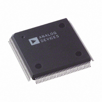
AD9887KS-140 Analog Devices Inc, AD9887KS-140 Datasheet - Page 26

AD9887KS-140
Manufacturer Part Number
AD9887KS-140
Description
IC INTRFACE ANALOG/DVI 160-MQFP
Manufacturer
Analog Devices Inc
Datasheet
1.AD9887AKSZ-100.pdf
(40 pages)
Specifications of AD9887KS-140
Rohs Status
RoHS non-compliant
Applications
Graphic Cards, VGA Interfaces
Interface
Analog and Digital
Voltage - Supply
3.15 V ~ 3.45 V
Package / Case
160-MQFP, 160-PQFP
Mounting Type
Surface Mount
Available stocks
Company
Part Number
Manufacturer
Quantity
Price
Company:
Part Number:
AD9887KS-140
Manufacturer:
ADI
Quantity:
440
Part Number:
AD9887KS-140
Manufacturer:
ADI/亚德诺
Quantity:
20 000
AD9887
Hex
Address
0FH
10H
11H
Read and
Write or
Read Only
R/W
R/W
RO
7:0
7:2
7:1
Bits
Default
Value
1
0
1
0
0
11
1
0
0
0
1
0
0
Table IX. Control Register Map (continued)
Register
Name
PLL and
Clamp Control
Mode
Control 2
Sync Detect/
Active
Interface
Function
Bit 7—HSYNC Polarity. Indicates the polarity of incoming HSYNC
signal to the PLL. (Logic 0 = Active Low, Logic 1 = Active High.)
Bit 6—Coast Polarity. Changes polarity of external COAST signal.
(Logic 0 = Active Low, Logic 1 = Active High.)
Bit 5—Clamp Function. Chooses between HSYNC for Clamp signal
or another external signal to be used for clamping. (Logic 0 = HSYNC,
Logic 1 = Clamp.)
Bit 4—Clamp Polarity. Valid only with external CLAMP signal. (Logic 0 =
Active Low, Logic 1 selects Active High.)
Bit 3—EXTCLK. Shuts down the PLL and allows the use of an external
clock to drive the part. (Logic 0 = use internal PLL, Logic 1 = bypass-
ing of the internal PLL.)
Bit 2—Red Clamp Select—Logic 0 selects clamp to ground. Logic 1
selects clamp to midscale (voltage at Pin 120).
Bit 1—Green Clamp Select—Logic 0 selects clamp to ground. Logic 1
selects clamp to midscale (voltage at Pin 111).
Bit 0—Blue Clamp Select—Logic 0 selects clamp to ground. Logic 1
selects clamp to midscale (voltage at Pin 101).
Bit 7—Clk Inv: Data clock output invert. (Logic 0 = Not Inverted,
Logic 1 = Inverted.) (Digital Interface Only.)
Bit 6—Pix Select: Selects either 1 or 2 pixels per clock mode.
(Logic 0 = 1 pixel/clock, Logic 1 = 2 pixels/clock.) (Digital Interface
Only.)
Bit 5, 4—Output Drive: Selects between high, medium, and low
output drive strength. (Logic 11 or 10 = High, 01 = Medium, and
00 = Low.)
Bit 3—P
1 = High Impedance.)
Bit 2—Sync Detect (SyncDT) Polarity. This bit sets the polarity
for the SyncDT output pin. (Logic 1 = Active High, Logic 0 =
Active Low.)
Bit 7—Analog Interface Hsync Detect. It is set to Logic 1 if Hsync
is present on the analog interface; otherwise it is set to Logic 0.
Bit 6—Analog Interface Sync-on-Green Detect. It is set to Logic 1
if sync is present on the green video input; otherwise it is set to 0.
Bit 5—Analog Interface Vsync Detect. It is set to Logic 1 if Vsync
is present on the analog interface; otherwise it is set to Logic 0.
Bit 4—Digital Interface Clock Detect. It is set to Logic 1 if the
clock is present on the digital interface; otherwise it is set to Logic 0.
Bit 3—AI: Active Interface. This bit indicates which interface is
active. (Logic 0 = Analog Interface, Logic 1 = Digital Interface.)
Bit 2—AHS: Active Hsync. This bit indicates which analog HSYNC
is being used. (Logic 0 = HSYNC Input Pin, Logic 1 = HSYNC
from Sync-on-Green.)
Bit 1—AVS: Active Vsync. This bit indicates which analog VSYNC
is being used. (Logic 0 = VSYNC input pin, Logic 1 = VSYNC from
sync separator.)
DO
: High Impedance Outputs. (Logic 0 = Normal, Logic


