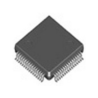
ICS1893Y-10 IDT, Integrated Device Technology Inc, ICS1893Y-10 Datasheet - Page 131

ICS1893Y-10
Manufacturer Part Number
ICS1893Y-10
Description
PHYCEIVER LOW PWR 3.3V 64-TQFP
Manufacturer
IDT, Integrated Device Technology Inc
Series
PHYceiver™r
Type
PHY Transceiverr
Specifications of ICS1893Y-10
Protocol
MII
Voltage - Supply
3.14 V ~ 3.47 V
Mounting Type
Surface Mount
Package / Case
64-TQFP, 64-VQFP
Lead Free Status / RoHS Status
Contains lead / RoHS non-compliant
Number Of Drivers/receivers
-
Lead Free Status / Rohs Status
Not Compliant
Other names
1893Y-10
800-1934-5
ICS1893Y-10
800-1934-5
ICS1893Y-10
Available stocks
Company
Part Number
Manufacturer
Quantity
Price
Company:
Part Number:
ICS1893Y-10
Manufacturer:
ICS
Quantity:
10 201
Company:
Part Number:
ICS1893Y-10
Manufacturer:
IDT, Integrated Device Technology Inc
Quantity:
10 000
Part Number:
ICS1893Y-10
Manufacturer:
ICS
Quantity:
20 000
Company:
Part Number:
ICS1893Y-10LF
Manufacturer:
ICS
Quantity:
5 978
Company:
Part Number:
ICS1893Y-10LF
Manufacturer:
IDT, Integrated Device Technology Inc
Quantity:
10 000
Company:
Part Number:
ICS1893Y-10LFT
Manufacturer:
IDT, Integrated Device Technology Inc
Quantity:
10 000
Company:
Part Number:
ICS1893Y-10T
Manufacturer:
IDT, Integrated Device Technology Inc
Quantity:
10 000
9.5.7 MII Management Interface Timing
ICS1893Y-10 Rev F 1/20/04
Table 9-14
timings of signals on the MDC and MDIO pins).
Table 9-14. MII Management Interface Timing
† The ICS1893Y-10 is tested at 25 MHz (a 40-ns period) with a 50-pF load. Designs must account for all board loading
Figure 9-8. MII Management Interface Timing Diagram
MDC
MDIO
(Output)
MDC
MDIO
(Input)
Period
of MDC.
Time
ICS1893Y-10 - Release
t1
t2
t3
t4
t5
t6
MDC Minimum High Time
MDC Minimum Low Time
MDC Period
MDC Rise Time to MDIO Valid
MDIO Setup Time to MDC
MDIO Hold Time after MDC
lists the significant time periods for the MII Management Interface timing (which consists of
t1
Parameter
t3
Copyright © 2004, Integrated Circuit Systems, Inc.
t2
t5
t4
t6
All rights reserved.
131
Figure 9-8
shows the timing diagram for the time periods.
Conditions
Chapter 9 DC and AC Operating Conditions
–
–
–
–
–
–
400†
Min.
160
160
10
10
0
Typ.
–
–
†
–
–
–
Max.
300
–
–
–
–
–
January, 2004
Units
ns
ns
ns
ns
ns
ns


