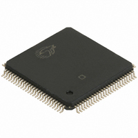
CY7C9689A-AXC Cypress Semiconductor Corp, CY7C9689A-AXC Datasheet - Page 38

CY7C9689A-AXC
Manufacturer Part Number
CY7C9689A-AXC
Description
IC TXRX HOTLINK 100LQFP
Manufacturer
Cypress Semiconductor Corp
Series
CY7Cr
Type
Transceiverr
Datasheet
1.CY7C9689A-AXC.pdf
(51 pages)
Specifications of CY7C9689A-AXC
Package / Case
100-LQFP
Voltage - Supply
4.5 V ~ 5.5 V
Mounting Type
Surface Mount
Product
PHY
Interface Type
Parallel
Supply Voltage (max)
6.5 V
Supply Voltage (min)
2 V
Supply Current
250 mA
Maximum Operating Temperature
+ 70 C
Minimum Operating Temperature
0 C
Mounting Style
SMD/SMT
Number Of Channels
2
Ic Interface Type
Parallel, Serial
Supply Voltage Range
4.5V To 5.5V
Operating Temperature Range
0°C To +70°C
Digital Ic Case Style
TQFP
No. Of Pins
100
Msl
MSL 3 - 168 Hours
No. Of Receivers
2
Rohs Compliant
Yes
Frequency Max
50MHz
Lead Free Status / RoHS Status
Lead free / RoHS Compliant
Number Of Drivers/receivers
-
Protocol
-
Lead Free Status / Rohs Status
Lead free / RoHS Compliant
Available stocks
Company
Part Number
Manufacturer
Quantity
Price
Company:
Part Number:
CY7C9689A-AXC
Manufacturer:
ALTERA
Quantity:
112
Company:
Part Number:
CY7C9689A-AXC
Manufacturer:
CY
Quantity:
86
Company:
Part Number:
CY7C9689A-AXC
Manufacturer:
CYPRESS
Quantity:
273
Company:
Part Number:
CY7C9689A-AXC
Manufacturer:
Cypress Semiconductor Corp
Quantity:
10 000
Part Number:
CY7C9689A-AXC
Manufacturer:
CYPRESS/赛普拉斯
Quantity:
20 000
Document #: 38-02020 Rev. *E
BIST Enable Inputs
There are separate BIST enable inputs for the transmit and
receive paths of the CY7C9689A. These inputs are both active
LOW; i.e., BIST is enabled in its respective section of the
device when the BIST enable input is determined to be at a
logic-0 level. Both BIST enable inputs are asynchronous; i.e.,
they are synchronized inside the CY7C9689A to the internal
state machines.
BIST Transmit Path
The transmit path operation with BIST is controlled by the
TXBISTEN input and overrides most other inputs (see
Figure
and TXBISTEN is recognized internally, all reads from the
Transmit FIFO are suspended and the BIST generator is
enabled to sequence out the 511 character repeating BIST
sequence. If the recognition occurs in the middle of a data
field, the following data is not transmitted at that time, but
remains in the Transmit FIFO. Once the TXBISTEN signal is
removed, the data in the Transmit FIFO is again available for
transmission. To ensure proper data handling at the desti-
nation, the transmit host controller should either use TXHALT
to prevent transmission of data at specific boundaries, or allow
the Transmit FIFO to completely empty before enabling BIST.
With transmit BIST enabled, the Transmit FIFO remains
available for loading of data. It may be written up to its normal
maximum limit while the BIST operation takes place. To allow
5). When the Transmit FIFO is enabled (not bypassed)
Enable TX BIST
Enable RX BIST
Start of TX BIST
Start of RX
BIST Wait
BIST match
Start of RX
Forced to indicate EMPTY by BIST
Figure 5. Built-In Self-Test Illustration
ERROR
LOOP
BIST
LOW to enable VLTN reads
LOW to enable FIFO Flags
Ignore these outputs
LOOP
BIST
Don’t Care
removal of stale data from the Transmit FIFO, it may also be
reset during a BIST operation. The reset operation proceeds
as documented, with the exception of the information
presented on the TXEMPTY FIFO status flag. Since this flag
is used to present BIST loop status, it continues to reflect the
state of the transmit BIST loop status until TXBISTEN is no
longer recognized internally. The completion of the reset
operation may still be monitored through the TXFULL FIFO
status flag.
The TXEMPTY flag, when used for transmit BIST progress
indication, continues to reflect the active HIGH or active LOW
settings determined by the UTOPIA or Cascade timing model
selected by EXTFIFO; i.e., when configured for the Cascade
timing model, the TXEMPTY and TXFULL FIFO flags are
active HIGH, when configured for the UTOPIA timing model
the TXEMPTY and TXFULL FIFO flags are active LOW. The
illustration in
When TXBISTEN is first recognized, the TXEMPTY flag is
clocked to a reset state, regardless of the addressed state of
the Transmit FIFO (if CE is LOW or not), but is not driven out
of the part unless CE has been sampled asserted (LOW).
Following this, on each completed pass through the BIST loop,
the TXEMPTY flag is set for one interface clock period (TXCLK
or REFCLK).
The TXEMPTY flag remains set until the interface is
addressed and the state of TXEMPTY has been observed. If
TXCLK
TXBISTEN
TXEMPTY
TXHALF
TXFULL
TXCMD[1:0]
TXSC/D
TXDATA[9:0]
TXEN
REFCLK
CE
RXEN
RXDATA[9:0]
RXSC/D
RXCMD[1:0]
VLTN
RXEMPTY
RXHALF
RXFULL
RXBISTEN
RXCLK
Figure 5
uses the UTOPIA conventions.
OUTA±
OUTB±
INA±
INB±
A/B
CY7C9689A
HIGH to select A
Page 38 of 51
[+] Feedback


