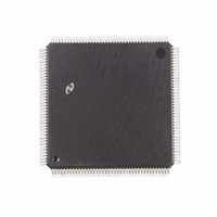
DP83905AVQB National Semiconductor, DP83905AVQB Datasheet - Page 6

DP83905AVQB
Manufacturer Part Number
DP83905AVQB
Description
IC CONTROLR AT/LAN TP IN 160PQFP
Manufacturer
National Semiconductor
Series
AT/LANTIC™r
Datasheet
1.DP83905AVQB.pdf
(80 pages)
Specifications of DP83905AVQB
Controller Type
AT, LAN Twisted-Pair Interface Controller
Voltage - Supply
4.75 V ~ 5.25 V
Current - Supply
100mA
Operating Temperature
0°C ~ 70°C
Mounting Type
Surface Mount
Package / Case
160-BFQFP
Lead Free Status / RoHS Status
Contains lead / RoHS non-compliant
Interface
-
Other names
*DP83905AVQB
Available stocks
Company
Part Number
Manufacturer
Quantity
Price
Company:
Part Number:
DP83905AVQB
Manufacturer:
Texas Instruments
Quantity:
10 000
Part Number:
DP83905AVQB
Manufacturer:
NS/国半
Quantity:
20 000
NETWORK INTERFACE PINS
EXTERNAL MEMORY SUPPORT
Pin No
7
8
10
58–50
48–45
43-40
31–25
22
21–15
33
32
37
2 0 Pin Description
Attachment Unit Interface TPI
Driver Types are I
X1 (OSCIN)
X2 (OSCOUT)
THIN
MSD0–7
CA0–7
DO DI SK
MSD8–15 or
CB0–7
MSA1–8 or
CC0–7
MSA9–15
MSRD
MSWR
BPCS
Pin Name
e
Input O
e
e
Twisted Pair Interface LED
I O I O
Type
DCDC
XTAL
XTAL
Output I O
I O I
MOS
MOS
MOS
MOS
MOS
MOS
MOS
O I
(Continued)
O
O
O
O
O
O
I
(Continued)
e
CRYSTAL OR EXTERNAL OSCILLATOR INPUT
CRYSTAL FEEDBACK OUTPUT Used in crystal connections only Should be left
completely unconnected when using an oscillator module
THIN CABLE This output is high if AT LANTIC Controller is configured for thin
cable It can be used to enable the DC-DC converter required by the thin ethernet
configuration
MEMORY SUPPORT DATA BUS CONFIGURATION REGISTER A INPUT
EEPROM SIGNALS
MSD0–7 When RESET is inactive these pins can be used to access external
memory and boot PROM
CA0–7 When RESET is active Configuration Register A is loaded with the data
value on these pins If the user puts an external pull-up on any of these pins then the
corresponding register bit is set to a 1 If the pin is left unconnected then the register
bit is 0
DO DI SK When RESET goes from an active to an inactive level AT LANTIC
Controller will read the contents of an EEPROM using these signals and load the
contents into internal registers These internal registers will then be mapped into the
space taken up by the PROM in the NE2000 and Ethercard PLUS16 After the
EEPROM read operation has completed these pins will revert to MSD0–2 (D0
MSD0 DI
MEMORY SUPPORT DATA BUS CONFIGURATION REGISTER B INPUT
MSD8–15 When RESET is inactive these pins can be used to access external
memory
CB0–7 When RESET is active Configuration Register B is loaded with the data
value on these pins If the user puts an external pull-up on any of these pins then the
corresponding register bit is set to a 1 If the pin is left unconnected then the register
bit is 0
MEMORY SUPPORT ADDRESS BUS CONFIGURATION REGISTER C INPUT
MSA1–8 When RESET is inactive these pins drive the memory support address
bus
CC0–7 When RESET is active Configuration Register C is loaded with the data
value on these pins If the user puts an external pull-up on any of these pins then the
corresponding register bit is set to a 1 If the pin is left unconnected then the register
bit is 0
MEMORY SUPPORT ADDRESS BUS MSA9–15 When RESET is inactive these
pins drive the memory support address bus When the memory is only 8 bits wide A0
will appear on A13 in compatible mode and on A15 in non-compatible mode
MEMORY SUPPORT BUS READ Strobes data from the external RAM into the AT
LANTIC Controller via the memory support data bus
MEMORY SUPPORT BUS WRITE Strobes data from the AT LANTIC Controller
into the external RAM via the memory support data bus
BOOT PROM CHIP SELECT Selects the boot PROM on the memory support data
bus
Bi-directional Output OCH
e
e
LED Drive MOS
MSD1 SK
6
e
e
Open Collector 3SH
e
MSD2)
CMOS Level Compatible XTAL
Description
e
TRI-STATE Output TTL
e
Crystal
e
TTL Compatible AUI
e
e


