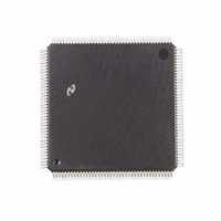
DP83905AVQB National Semiconductor, DP83905AVQB Datasheet - Page 41

DP83905AVQB
Manufacturer Part Number
DP83905AVQB
Description
IC CONTROLR AT/LAN TP IN 160PQFP
Manufacturer
National Semiconductor
Series
AT/LANTIC™r
Datasheet
1.DP83905AVQB.pdf
(80 pages)
Specifications of DP83905AVQB
Controller Type
AT, LAN Twisted-Pair Interface Controller
Voltage - Supply
4.75 V ~ 5.25 V
Current - Supply
100mA
Operating Temperature
0°C ~ 70°C
Mounting Type
Surface Mount
Package / Case
160-BFQFP
Lead Free Status / RoHS Status
Contains lead / RoHS non-compliant
Interface
-
Other names
*DP83905AVQB
Available stocks
Company
Part Number
Manufacturer
Quantity
Price
Company:
Part Number:
DP83905AVQB
Manufacturer:
Texas Instruments
Quantity:
10 000
Part Number:
DP83905AVQB
Manufacturer:
NS/国半
Quantity:
20 000
5 0 Register Descriptions
Note In the figure above registers are shown as 8- or 16-bits wide Although some registers are 16-bit intemal registers all registers are accessed as 8-bit
5 4 DP8390 Core DMA Registers
The DMA Registers are partitioned into groups Transmit
Receive and Remote DMA Registers The Transmit regis-
ters are used to initialize the Local DMA Channel for trans-
mission of packets while the Receive Registers are used to
initialize the Local DMA Channel for packet Reception The
Page Stop Page Start Current and Boundary Registers are
used by the Buffer Management Logic to supervise the Re-
ceive Buffer Ring The Remote DMA Registers are used to
initialize the Remote DMA
Transmit DMA Registers
TRANSMIT PAGE START REGISTER (TPSR)
This register points to the assembled packet to be transmit-
ted Only the eight higher order addresses are specified
since all transmit packets are assembled on 256-byte page
boundaries The bit assignment is shown below The values
placed in bits D7–D0 will be used to initialize the higher
order address (A8–A15) of the Local DMA for transmission
The lower order bits (A7–A0) are initialized to zero
registers Thus the 16-bit Transmit Byte Count Register is broken into two 8-bit registers TBCR0 and TBCR1 Also TPSR PSTART PSTOP CURR and
BNRY only check or control the upper 8 bits of address information on the bus Thus they are shifted to positions 15–8 in the diagram above
(Continued)
FIGURE 24 DMA Register
41
Bit Assignment
TRANSMIT BYTE COUNT REGISTER 0 1 (TBCR0 TBCR1)
These two registers indicate the length of the packet to be
transmitted in bytes The count must include the number of
bytes in the source destination length and data fields The
maximum number of transmit bytes allowed is 64 kbytes
The AT LANTIC Controller will not truncate transmissions
longer than 1500 bytes The bit assignment is shown below
Local DMA Receive Registers
PAGE START STOP REGISTERS (PSTART PSTOP)
The Page Start and Page Stop Registers program the start-
ing and stopping address of the Receive Buffer Ring Since
TPSR
TBCR1
TBCR0
A15
(A7 – A0 Initialized to 0)
7
L15
L7
7
7
A14
6
L14
L6
6
6
A13
L13
5
L5
5
5
A12
L12
4
L4
4
4
TL F 11498 – 21
A11
L11
3
L3
3
3
A10
L10
L2
2
2
2
A9
L9
L1
1
1
1
A8
L8
L0
0
0
0


