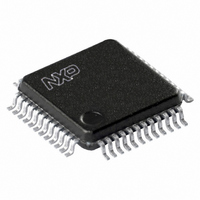
TDA8007BHL/C3,118 NXP Semiconductors, TDA8007BHL/C3,118 Datasheet - Page 32

TDA8007BHL/C3,118
Manufacturer Part Number
TDA8007BHL/C3,118
Description
IC INTERFACE CARD MP 48-LQFP
Manufacturer
NXP Semiconductors
Datasheet
1.TDA8007BHLC3118.pdf
(51 pages)
Specifications of TDA8007BHL/C3,118
Controller Type
Multiprotocol IC Card Interface
Interface
Parallel
Voltage - Supply
2.7 V ~ 6 V
Current - Supply
315mA
Operating Temperature
-40°C ~ 85°C
Mounting Type
Surface Mount
Package / Case
48-LQFP
Maximum Operating Temperature
+ 85 C
Minimum Operating Temperature
- 40 C
Mounting Style
SMD/SMT
Lead Free Status / RoHS Status
Lead free / RoHS Compliant
Other names
568-3520-2
935272525118
TDA8007BHLBE-T
935272525118
TDA8007BHLBE-T
Available stocks
Company
Part Number
Manufacturer
Quantity
Price
Company:
Part Number:
TDA8007BHL/C3,118
Manufacturer:
NXP Semiconductors
Quantity:
10 000
NXP Semiconductors
TDA8007BHL
Product data sheet
8.4 Step up converter
8.5 ISO 7816 security
Except for the V
powered by V
for the ISO contacts supply. When a card session is requested by the microcontroller, the
sequencer first enables the step-up converter (a switched capacitors type) which is
clocked by an internal oscillator at a frequency of approximately 2.5 MHz.
Supposing that V
The recognition of the supply voltage is done by the TDA8007BHL/C4 at approximately
3.5 V.
The output voltage V
reference for all other card contacts.
The correct sequence during activation and deactivation of the cards is ensured by two
specific sequencers, the clock is defined by a division ratio of the internal oscillator.
Activation (bit START = 1 in registers PCR1 or PCR2) is only possible if the card is
present (pin PRES is active high with an internal current source to ground) and if the
supply voltage is correct (voltage supervisor not active).
The presence of the cards is signalled to the microcontroller by register HSR. Bits PR1
or PR2 in register MSR are set if card 1 or 2 is present. Bits PRL1 or PRL2 are set if
pins PRES1 or PRES2 have been toggled.
During a session, the sequencer performs an automatic emergency deactivation on one
card in the event of card take-off, or short-circuit. Both cards are automatically deactivated
in the event of a supply voltage drop, or overheating. Register HSR is updated and the
INT line falls so that the system microcontroller is aware of what happened.
•
•
•
V
– For V
– For V
V
– For V
– For V
V
– T he step-up converter acts as a voltage follower for any value of V
CC
CC
CC
at approximately 5.5 V
V
V
to V
UP
UP
= 5 V
= 3 V
= 1.8 V
UP
at approximately 5.5 V
at approximately 4.0 V
DD
DD
DD
DD
DD
= 3 V the step-up converter acts as a voltage tripler with regulation of V
= 5 V the step-up converter acts as a voltage doubler with regulation of
= 3 V the step-up converter acts as a voltage doubler with regulation of
= 5 V the step-up converter acts as a voltage follower and V
All information provided in this document is subject to legal disclaimers.
CC
, and V
CC
generator and the other cards contacts buffers, the whole circuit is
is the maximum of V
UP
Rev. 8 — 11 January 2011
DDA
is fed to the V
. If the supply voltage is 2.5 V, then a higher voltage is needed
CC
CC1
generators. V
and V
CC2
, then the possible situations are:
CC
Multiprotocol IC card interface
and GNDC are used as a
TDA8007BHL
© NXP B.V. 2011. All rights reserved.
DD
DD
.
is applied
32 of 51
UP


