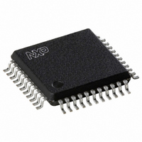
UDA1338H/N1,518 NXP Semiconductors, UDA1338H/N1,518 Datasheet - Page 43

UDA1338H/N1,518
Manufacturer Part Number
UDA1338H/N1,518
Description
IC AUDIO CODER/DECODER 44QFP
Manufacturer
NXP Semiconductors
Type
Stereo Audior
Datasheet
1.UDA1338HN1518.pdf
(55 pages)
Specifications of UDA1338H/N1,518
Package / Case
44-MQFP, 44-PQFP
Data Interface
Serial
Resolution (bits)
24 b
Number Of Adcs / Dacs
5 / 6
Sigma Delta
No
S/n Ratio, Adcs / Dacs (db) Typ
100 / 114
Voltage - Supply, Analog
2.7 V ~ 3.6 V
Voltage - Supply, Digital
2.7 V ~ 3.6 V
Operating Temperature
-20°C ~ 85°C
Mounting Type
Surface Mount
Product
General Purpose Audio Amplifiers
Available Set Gain
26 dB
Operating Supply Voltage
3.3 V
Supply Current
30 mA, 20 mA, 31 mA
Maximum Operating Temperature
+ 85 C
Mounting Style
SMD/SMT
Audio Load Resistance
22 KOhms
Input Signal Type
Single
Minimum Operating Temperature
- 20 C
Output Signal Type
Differential
Supply Voltage (max)
3.6 V
Supply Voltage (min)
2.7 V
Output Type
Differential
Lead Free Status / RoHS Status
Lead free / RoHS Compliant
Lead Free Status / RoHS Status
Lead free / RoHS Compliant, Lead free / RoHS Compliant
Other names
935268945518
UDA1338HB-T
UDA1338HB-T
UDA1338HB-T
UDA1338HB-T
Available stocks
Company
Part Number
Manufacturer
Quantity
Price
Company:
Part Number:
UDA1338H/N1,518
Manufacturer:
NXP Semiconductors
Quantity:
10 000
NXP Semiconductors
Table 66:
V
referenced to ground (pins V
[1]
[2]
16. Timing
Table 67:
V
f
UDA1338H
Product data sheet
Symbol
Single-ended mode
V
ΔV
(THD + N)/S
S/N
α
Symbol
System clock; see
T
t
t
I
Serial data of audio ADC and DAC; see
f
T
t
t
t
t
t
t
t
s
CWL
CWH
2
BCK
BCKH
BCKL
r
f
su(WS)
h(WS)
su(DATAI)
DDD
DDD
cs
sys
cy(BCK)
o(rms)
S-bus interface
= 48 kHz; unless otherwise specified.
o
The input voltage can be up to 2 V (RMS) when the current through the ADC input pin is limited to approximately 1 mA by using a series
resistor.
The input voltage to the ADC scales proportionally with the power supply voltage.
= V
= V
DDA(AD)
DDA(AD)
AC characteristics
Timing
Parameter
system clock cycle time
system clock LOW time
system clock HIGH time
audio bit clock frequency
BCK cycle time
bit clock HIGH time
bit clock LOW time
rise time
fall time
word select set-up time
word select hold time
data input set-up time
= V
= V
Parameter
output voltage (RMS value)
output voltage unbalance
between channels
total harmonic
distortion-plus-noise to signal
ratio
signal-to-noise ratio
channel separation
DDA(DA)
DDA(AD)
Figure 16
= 3.3 V; f
= 2.7 V to 3.6 V; T
SS
); unless otherwise specified.
…continued
i
= 1 kHz; T
Figure 17
All information provided in this document is subject to legal disclaimers.
amb
amb
= −20
Conditions
at 0 dBFS digital input
at 0 dBFS
at −20 dBFS
at −60 dBFS; A-weighted
code = 0; A-weighted
Rev. 04 — 18 May 2010
= 25
Conditions
f
f
f
f
f
f
f
f
sys
sys
sys
sys
sys
sys
sys
sys
°
= 256f
= 384f
= 512f
= 768f
< 19.2 MHz
≥ 19.2 MHz
< 19.2 MHz
≥ 19.2 MHz
C to +85
°
C; R
L
s
s
s
s
= 22 kΩ; sampling frequency f
°
C; typical timing specified at sampling frequency
[1]
[2]
Min.
35
23
17
17
0.3T
0.4T
0.3T
0.4T
-
-
30
30
-
-
10
10
10
Multichannel audio coder-decoder
Min.
-
-
-
-
-
-
-
sys
sys
sys
sys
s
Typ.
1.0
<0.1
−90
−85
−45
110
114
= 48 kHz; all voltages
Typ.
81
54
41
27
-
-
-
-
-
-
-
-
-
-
-
-
-
UDA1338H
© NXP B.V. 2010. All rights reserved.
Max.
-
-
-
-
-
-
-
Max.
780
520
390
260
0.7T
0.6T
0.7T
0.6T
12.8
78
-
-
20
20
-
-
-
sys
sys
sys
sys
Unit
dB
dB
dB
dB
dB
dB
V
43 of 55
Unit
ns
ns
ns
ns
ns
ns
ns
ns
MHz
ns
ns
ns
ns
ns
ns
ns
ns


