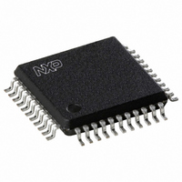
UDA1338H/N1,518 NXP Semiconductors, UDA1338H/N1,518 Datasheet - Page 27

UDA1338H/N1,518
Manufacturer Part Number
UDA1338H/N1,518
Description
IC AUDIO CODER/DECODER 44QFP
Manufacturer
NXP Semiconductors
Type
Stereo Audior
Datasheet
1.UDA1338HN1518.pdf
(55 pages)
Specifications of UDA1338H/N1,518
Package / Case
44-MQFP, 44-PQFP
Data Interface
Serial
Resolution (bits)
24 b
Number Of Adcs / Dacs
5 / 6
Sigma Delta
No
S/n Ratio, Adcs / Dacs (db) Typ
100 / 114
Voltage - Supply, Analog
2.7 V ~ 3.6 V
Voltage - Supply, Digital
2.7 V ~ 3.6 V
Operating Temperature
-20°C ~ 85°C
Mounting Type
Surface Mount
Product
General Purpose Audio Amplifiers
Available Set Gain
26 dB
Operating Supply Voltage
3.3 V
Supply Current
30 mA, 20 mA, 31 mA
Maximum Operating Temperature
+ 85 C
Mounting Style
SMD/SMT
Audio Load Resistance
22 KOhms
Input Signal Type
Single
Minimum Operating Temperature
- 20 C
Output Signal Type
Differential
Supply Voltage (max)
3.6 V
Supply Voltage (min)
2.7 V
Output Type
Differential
Lead Free Status / RoHS Status
Lead free / RoHS Compliant
Lead Free Status / RoHS Status
Lead free / RoHS Compliant, Lead free / RoHS Compliant
Other names
935268945518
UDA1338HB-T
UDA1338HB-T
UDA1338HB-T
UDA1338HB-T
Available stocks
Company
Part Number
Manufacturer
Quantity
Price
Company:
Part Number:
UDA1338H/N1,518
Manufacturer:
NXP Semiconductors
Quantity:
10 000
NXP Semiconductors
UDA1338H
Product data sheet
11.3 System settings
Table 22:
Table 23:
Bit
Symbol
Reset
default
Bit
Symbol
Reset
default
Bit
15
14 to 13
12
11
10
9 to 8
7 to 6
5 to 4
3
2
1
0
System register (address 00h)
Description of system register bits
15
RST
-
7
OP1
0
Symbol
RST
VFS[1:0] Voice ADC sampling frequency. A 2-bit value to select the voice ADC
VCE
VAP
DSD
SC[1:0]
OP[1:0]
FS[1:0]
ACE
ADP
DCE
DAP
All information provided in this document is subject to legal disclaimers.
14
VFS1
0
6
OP0
0
Description
Reset. A 1-bit value to initialize the L3-bus registers with the default
settings by writing bit RST = 1. If bit RST = 0, there is no reset.
sampling frequency. Default 00; see
Voice ADC clock enable. A 1-bit value to enable the voice ADC clock. If
bit VCE = 1 (default), then the clock is enabled; if bit VCE = 0, then the
clock is disabled.
Voice ADC power control. A 1-bit value to reduce the power
consumption of the voice ADC. If bit VAP = 1, then the state is power-on; if
bit VAP = 0 (default), then the state is power-off.
DSD mode selection. A 1-bit value to select the DSD mode. If
bit DSD = 1, then the DSD mode; if bit DSD = 0 (default), then the normal
mode.
System clock frequency. A 2-bit value to select the used external clock
frequency. 128f
bit DVD = 1. Default 00; see
Operating mode selection. A 2-bit value to select the operation mode of
the audio ADC and DAC. Default 00; see
Sampling frequency. A 2-bit value to select the sampling frequency of the
audio ADC and DAC in the WS mode. Default 01; see
ADC clock enable. A 1-bit value to enable the audio ADC clock. If
bit ACE = 1 (default), then the clock is enabled; if bit ACE = 0, then the
clock is disabled.
ADC power control. A 1-bit value to reduce the power consumption of the
audio ADC. If bit ADP = 1, then the state is power-on; if bit ADP = 0
(default), then the state is power-off.
DAC clock enable. A 1-bit value to enable the DAC clock. If bit DCE = 1
(default), then the clock is enabled; if bit DCE = 0, then the clock is
disabled.
DAC power control. A 1-bit value to reduce the power consumption of the
DAC. If bit DAP = 1, then the state is power-on; if bit DAP = 0 (default),
then the state is power-off.
Rev. 04 — 18 May 2010
VFS0
13
0
5
FS1
0
s
system clock for the DAC can be used by setting
12
VCE
1
4
FS0
1
Table
11
VAP
0
3
ACE
1
Multichannel audio coder-decoder
25.
Table
Table
24.
10
DSD
0
2
ADP
0
26.
UDA1338H
SC1
0
1
DCE
1
9
© NXP B.V. 2010. All rights reserved.
Table
27.
8
SC0
0
0
DAP
0
27 of 55


