GC80503CSM66166SL388 Intel, GC80503CSM66166SL388 Datasheet - Page 45
GC80503CSM66166SL388
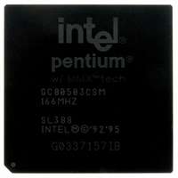
Manufacturer Part Number
GC80503CSM66166SL388
Description
IC MPU 1.9V PENTI 166MHZ 352BGA
Manufacturer
Intel
Datasheet
1.GC80503CSM66166SL388.pdf
(62 pages)
Specifications of GC80503CSM66166SL388
Rohs Status
RoHS non-compliant
Processor Type
Pentium I w/MMX
Features
66MHz Bus
Speed
166MHz
Voltage
1.9V
Mounting Type
Surface Mount
Package / Case
352-BGA
Other names
821225


4.3
4.3.1
4.3.2
Datasheet
AC Specifications
The AC specifications of the low-power embedded Pentium processor with MMX technology
consist of setup times, hold times, and valid delays at 0 pF.
Power and Ground
For clean on-chip power distribution, the PPGA has 25 V
and 53 V
inputs.
Power and ground connections must be made to all external V
circuit board, all V
voltage determined by package type/frequency). All V
plane. All V
of V
Decoupling Recommendations
Liberal decoupling capacitance should be placed near the processor. The processor’s large address
and data buses can cause transient power surges, particularly when driving large capacitive loads.
Low inductance capacitors and interconnects are recommended for best high frequency electrical
performance. Inductance can be reduced by shortening circuit board traces between the processor
and decoupling capacitors as much as possible. These capacitors should be evenly distributed
around each component on the power plane. Capacitor values should be chosen to ensure they
eliminate both low and high frequency noise components.
Power transients also occur as the processor rapidly transitions from a low level power
consumption to a high level one (or high to low power transition). A typical example would be
entering or exiting the Stop Grant state. Another example would be executing a HALT instruction,
causing the processor to enter the Auto HALT Powerdown state, or transitioning from HALT to the
Normal state. All of these examples may cause abrupt changes in the power being consumed by the
processor.
Note that the Auto HALT Powerdown feature is always enabled even when other power
management features are not implemented.
Bulk storage capacitors with a low ESR (Effective Series Resistance) in the 10 to 100 µf range are
required to maintain a regulated supply voltage during the interval between the time the current
load changes and the point that the regulated power supply output can react to the change in load.
In order to reduce the ESR, it may be necessary to place several bulk storage capacitors in parallel.
These capacitors should be placed near the processor on both V
that the supply voltages stay within specified limits during changes in the supply current during
operation.
CC2
, V
SS
CC3
(ground) inputs. For the HL-PBGA package, there are 42 V
SS
pins must be connected to a V
and V
Low-Power Embedded Pentium
CC2
SS
pins must be connected to a proper voltage V
pins.
SS
plane. Please refer to Table 2 on page 17 for the list
CC3
®
Processor with MMX™ Technology
CC2
pins must be connected to a 2.5 V V
(core power), 28 V
CC2
CC2
, V
plane and V
CC2
CC3
CC3
plane or island (core
and V
, 37 V
CC3
SS
CC3
CC2
pins. On the
plane to ensure
(I/O power)
and 72 V
CC3
SS
45
,
Related parts for GC80503CSM66166SL388
Image
Part Number
Description
Manufacturer
Datasheet
Request
R

Part Number:
Description:
Microprocessor: Intel Celeron M Processor 320 and Ultra Low Voltage Intel Celeron M Processor at 600MHz
Manufacturer:
Intel Corporation
Part Number:
Description:
Intel 82550 Fast Ethernet Multifunction PCI/CardBus Controller
Manufacturer:
Intel Corporation
Datasheet:
Part Number:
Description:
Intel StrataFlash memory 32 Mbit. Access speed 120 ns
Manufacturer:
Intel Corporation
Datasheet:
Part Number:
Description:
Intel StrataFlash memory 32 Mbit. Access speed 120 ns
Manufacturer:
Intel Corporation
Datasheet:
Part Number:
Description:
Intel StrataFlash memory 64 Mbit. Access speed 150 ns
Manufacturer:
Intel Corporation
Datasheet:
Part Number:
Description:
Intel StrataFlash memory 32 Mbit. Access speed 100 ns
Manufacturer:
Intel Corporation
Datasheet:
Part Number:
Description:
DA28F640J5A-1505 Volt Intel StrataFlash Memory
Manufacturer:
Intel Corporation
Datasheet:
Part Number:
Description:
5 Volt Intel StrataFlash?? Memory
Manufacturer:
Intel Corporation
Datasheet:
Part Number:
Description:
5 Volt Intel StrataFlash?? Memory
Manufacturer:
Intel Corporation
Part Number:
Description:
Intel 6300ESB I/O Controller Hub
Manufacturer:
Intel Corporation
Datasheet:
Part Number:
Description:
Intel 82801DB I/O Controller Hub (ICH4), Pb-Free SLI
Manufacturer:
Intel Corporation
Datasheet:
Part Number:
Description:
Intel 82801FB I/O Controller Hub (ICH6)
Manufacturer:
Intel Corporation
Datasheet:
Part Number:
Description:
Intel Strataflash Memory28F128J3 28F640J3 28F320J3
Manufacturer:
Intel Corporation
Datasheet:
Part Number:
Description:
Controllers, Intel 430TX PCIset: 82439TX System Controller (MTXC)
Manufacturer:
Intel Corporation