DLP-245SY-G DLP Design Inc, DLP-245SY-G Datasheet - Page 4
DLP-245SY-G
Manufacturer Part Number
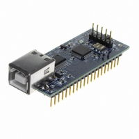
DLP-245SY-G
Description
MODULE USB-MCU FT245RL W/SX48
Manufacturer
DLP Design Inc
Datasheet
1.DLP-245SY-G.pdf
(14 pages)
Specifications of DLP-245SY-G
Module/board Type
Development Board
Product
Microcontroller Modules
Data Bus Width
8 bit
Core Processor
SX48
Clock Speed
50 MHz
Interface Type
USB
Flash
4 KBytes
Operating Supply Voltage
5 V
Board Size
56.8 mm x 22.9 mm x 22.3 mm
Lead Free Status / RoHS Status
Lead free / RoHS Compliant
For Use With/related Products
USB
Lead Free Status / RoHS Status
Lead free / RoHS Compliant, Lead free / RoHS Compliant
Other names
813-1006


FT_EE_UASize gets its size, FT_EE_UAWrite writes data into it, and FT_EE_UARead is used to
read its contents.
Download FTDI Application Notes AN232-03, AN232-05, AN232-06, and AN232-07 for
detailed instructions on how to install and remove the drivers.
EEPROM WRITE UTILITY
The DLP-245SY-G has the option to accept manufacturer-specific information that is written into
the EEPROM area of the FT245RL. Parameters that can be programmed include the VID and
the PID identifiers, the manufacturer's product string, and a serial number.
MPROG is the latest EEPROM serializer utility from FTDI for the FT245RL device. MPROG uses
the new D2XX drivers and will work on Windows 98, Windows ME, and Windows 2000/XP
platforms. You must install the latest release of the D2XX drivers in order to run this application.
QUICK START GUIDE
This guide requires the use of a Windows 98/2000/XP PC that is equipped with a USB port.
1. Download the DLL version of the device drivers from either dlpdesign.com or ftdichip.com.
2. The board can be configured to receive its operating power from the USB port or from user
3. Connect the DLP-245SY-G board to the PC via a standard A-B, 6-foot USB cable. This
Unzip the drivers onto a blank floppy disk or into a folder on the hard drive.
electronics. Pins 18, 19, and 20 allow for this configuration. (Refer to the Pinout Description
in the next section for a detailed description of the DLP-245SY-G electrical interface.)
Note: The board will not operate until a power source has been selected as mentioned in
Step 2.
action initiates the loading of the USB drivers. When prompted, select the folder where the
DLL version of the device drivers was stored in Step 1. Windows will then complete the
installation of the device drivers for the DLP-245SY-G. The next time the DLP-245SY-G is
4
Related parts for DLP-245SY-G
Image
Part Number
Description
Manufacturer
Datasheet
Request
R

Part Number:
Description:
MODULE USB-TO-TTL SRL UART CONV
Manufacturer:
DLP Design Inc
Datasheet:

Part Number:
Description:
MODULE USB-TO-TTL PARL FIFO CONV
Manufacturer:
DLP Design Inc
Datasheet:

Part Number:
Description:
KIT DEV DLP LIGHTCOMANDER
Manufacturer:
Logic
Datasheet:

Part Number:
Description:
MODULE DATA-ACQUISITION 8-CH
Manufacturer:
DLP Design Inc
Datasheet:

Part Number:
Description:
MODULE DATA-ACQUISITION 20-CH
Manufacturer:
DLP Design Inc
Datasheet:

Part Number:
Description:
RFID READER/WRITER SNGL-CH OEM
Manufacturer:
DLP Design Inc
Datasheet:

Part Number:
Description:
Interface Modules & Development Tools DLP-245PL PACKAGED w/CCS Compiler
Manufacturer:
DLP Design Inc

Part Number:
Description:
Interface Modules & Development Tools DLP-245PB-G BOARD + CCS Compiler
Manufacturer:
DLP Design Inc
Datasheet:

Part Number:
Description:
Interface Modules & Development Tools DLP-TILT SENSOR ACCEL VIBRATION
Manufacturer:
DLP Design Inc

Part Number:
Description:
MODULE USB-MCU FT245RL W/16F877A
Manufacturer:
DLP Design Inc
Datasheet:

Part Number:
Description:
MODULE USB-TO-FPGA TRAINING TOOL
Manufacturer:
DLP Design Inc
Datasheet:

Part Number:
Description:
MODULE USB-MCU FT232R W/18F2410
Manufacturer:
DLP Design Inc
Datasheet:

Part Number:
Description:
MODULE USB-MCU FT2232D W/16F877A
Manufacturer:
DLP Design Inc
Datasheet:

Part Number:
Description:
MODULE USB-TO-FPGA SPARTAN3
Manufacturer:
DLP Design Inc
Datasheet:

Part Number:
Description:
MOD USB-MCU FT245RL W/18LF8722
Manufacturer:
DLP Design Inc
Datasheet: