DLP-232PC DLP Design Inc, DLP-232PC Datasheet - Page 7
DLP-232PC
Manufacturer Part Number
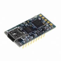
DLP-232PC
Description
MODULE USB-MCU FT232R W/18F2410
Manufacturer
DLP Design Inc
Datasheet
1.DLP-232PC.pdf
(10 pages)
Specifications of DLP-232PC
Module/board Type
Microcontroller Module
Interface Type
USB
Operating Supply Voltage
0 V to 5 V
Product
Interface Modules
For Use With/related Products
USB
Lead Free Status / RoHS Status
Lead free / RoHS Compliant
Lead Free Status / RoHS Status
Lead free / RoHS Compliant, Lead free / RoHS Compliant
Other names
813-1003


A/D Setup
LED Commands
Note 1 – Data is returned in either the form of ASCII characters (ex: 1.25V, 78.2°F) or binary (raw data)
depending upon the current mode. The power-up default mode is ASCII such that data is easily read using a
terminal emulator program.
Note 2 – Requires DS18B20 digital temperature sensor (purchased separately). See Section 8.0 of this
document for connection details.
8.0 TEMPERATURE
Up to 14 DS18B20 digital temperature sensors can be connected to the DLP-232PC. For best
performance, use Category 5 type computer cable to connect the sensors to the DLP-232PC. Two
pairs of wires in the Cat 5 cable are required for the connection. The first pair is for Power (5V) and
Ground, and the second pair is designated as Data and Ground. In addition, a pull-up resistor is
required for the data line in the range if 1.5K-4.7K Ohms. Figure 1 shows an example of this
connection using I/O Channel 11:
The first time temperature data is requested, a value of 999.99° (0xFF x 2 if in Binary Mode) is
returned. Subsequent reads will return valid temperature data if a temperature sensor is properly
configured and connected to the specified I/O port. If no sensor is connected, a Temperature
command will always return 999.99°. Please note that the PAR versions of the sensor
(DS18B20+PAR) will not work with the 232PC firmware.
Rev. 1.6 (October 2010)
%
w
u
v
x
y
#
$
z
{
}
DLP-232PC
0x7A
0x7B
0x7D
0x75
0x76
0x77
0x78
0x79
0x23
0x24
0x25
No Analogs
CH1 Only
CH1 and CH2
CH1,2,3
CH1,2,3,4
CH1,2,3,4,5
CH1,2,3,4,5,6
CH1 – CH7
CH1 – CH8
LED Off
LED On
A/D Converter disabled
A/D active on Channel 1 only
A/D active on Channels 1 and 2
A/D active on Channels 1 through 3
A/D active on Channels 1 through 4
A/D active on Channels 1 through 5
A/D active on Channels 1 through 6
A/D active on Channels 1 through 7
A/D active on Channels 1 through 8
FIGURE 1
7
Pin 1
DS18B20
© DLP Design, Inc.
2. DATA
3. VCC
1. GND
Related parts for DLP-232PC
Image
Part Number
Description
Manufacturer
Datasheet
Request
R

Part Number:
Description:
MODULE DATA-ACQUISITION 20-CH
Manufacturer:
DLP Design Inc
Datasheet:

Part Number:
Description:
Zigbee / 802.15.4 Modules & Development Tools USE 626-DLP-RF2-Z
Manufacturer:
DLP Design Inc
Datasheet:
Part Number:
Description:
Zigbee / 802.15.4 Modules & Development Tools TTL SERIAL INTERFACE MODULE
Manufacturer:
DLP Design Inc
Datasheet:

Part Number:
Description:
MODULE USB-TO-TTL SRL UART CONV
Manufacturer:
DLP Design Inc
Datasheet:

Part Number:
Description:
Interface Modules & Development Tools FLASH2 TARGET BOARD 18F2321 w/IDE 2k Ltd
Manufacturer:
DLP Design Inc

Part Number:
Description:
Interface Modules & Development Tools FLASH2 TARGET BOARD 16F917 w/IDE 2k Ltd
Manufacturer:
DLP Design Inc

Part Number:
Description:
Interface Modules & Development Tools FLASH2 TARGET BOARD 18F4420 w/IDE 2k Ltd
Manufacturer:
DLP Design Inc
Part Number:
Description:
Zigbee / 802.15.4 Modules & Development Tools TTL SERIAL INTERFACE MODULE
Manufacturer:
DLP Design Inc
Datasheet:

Part Number:
Description:
Interface Modules & Development Tools USB FPGA Module w/ Xilinx XC3S400A
Manufacturer:
DLP Design Inc
Datasheet:

Part Number:
Description:
Interface Modules & Development Tools Dual Ch USB Adapter w/ FTDI FT2232H
Manufacturer:
DLP Design Inc
Datasheet:

Part Number:
Description:
MODULE USB-MCU FT245RL W/16F877A
Manufacturer:
DLP Design Inc
Datasheet:

Part Number:
Description:
MODULE USB-TO-FPGA TRAINING TOOL
Manufacturer:
DLP Design Inc
Datasheet:

Part Number:
Description:
MODULE USB-MCU FT245RL W/SX48
Manufacturer:
DLP Design Inc
Datasheet:

Part Number:
Description:
MODULE USB-MCU FT2232D W/16F877A
Manufacturer:
DLP Design Inc
Datasheet:

Part Number:
Description:
MODULE USB-TO-FPGA SPARTAN3
Manufacturer:
DLP Design Inc
Datasheet: