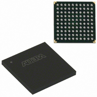
EPM570GF100C5N Altera, EPM570GF100C5N Datasheet - Page 8

EPM570GF100C5N
Manufacturer Part Number
EPM570GF100C5N
Description
IC MAX II CPLD 570 LE 100-FBGA
Manufacturer
Altera
Series
MAX® IIr
Datasheets
1.EPM240GT100C5N.pdf
(6 pages)
2.EPM240GT100C5N.pdf
(88 pages)
3.EPM240GM100C5N.pdf
(10 pages)
Specifications of EPM570GF100C5N
Programmable Type
In System Programmable
Delay Time Tpd(1) Max
5.4ns
Voltage Supply - Internal
1.71 V ~ 1.89 V
Number Of Logic Elements/blocks
570
Number Of Macrocells
440
Number Of I /o
76
Operating Temperature
0°C ~ 85°C
Mounting Type
Surface Mount
Package / Case
100-FBGA
Voltage
1.8V
Memory Type
FLASH
Number Of Logic Elements/cells
570
Lead Free Status / RoHS Status
Lead free / RoHS Compliant
Features
-
Other names
544-1730
Available stocks
Company
Part Number
Manufacturer
Quantity
Price
MAX II Device Family
8
Preliminary
Note to
(1)
EPM1270 (ES)
EPM1270 (Production)
Table 5. t
Numbers are approximate and do not represent specifications.
Table
Device
CONFIG
5:
, POR Release, & V
POR & Brown-Out Reset Voltage Levels
EPM1270 devices have POR circuits to monitor V
levels during power-up. The POR circuit monitors these voltages
triggering download from the non-volatile configuration flash memory
(CFM) block to the SRAM logic maintaining tri-state of the I/O pins
before and during this process. When the EPM1270 device enters user
mode, the POR circuit releases the I/O pins to user functionality and
continues to monitor the V
brown-out condition. If there is a V
operational level during user mode, the POR circuit resets the device and
re-triggers an SRAM download. For EPM1270 ES devices, the POR re-
trigger voltage level for a V
high as 2.1 V, allowing for 275 mV of V
minimum. EPM1270 ES device users should ensure that the power
supply noise does not lead V
1
Also, during power-up, production devices have a lower POR release
voltage and increased configuration time (t
ES devices. The MAX II Handbook specification for instant-on time
(t
operation begins before this specified worst-case period of time and
voltage because the POR release voltage for internal configuration occurs
below 2.375 V. This actual configuration start voltage and the t
differs between EPM1270 ES and EPM1270 production devices.
shows the POR release and trip voltages and t
production and ES devices.
Figure 2
characteristics of EPM1270 ES devices compared to EPM1270 production
devices.
CONFIG
200 µs
300 µs
t
CONFIG
CCINT
) is referenced from 2.375-V minimum V
shows the relative power-up and the power-down
Production devices have a V
brown-out conditions down to 1.4 V.
Brown-Out Voltage in EPM1270 ES & Production Devices
POR Release Voltage During
Power-Up
CCINT
2.2 V
1.7 V
CCINT
CCINT
(not V
(1)
sag or brown-out condition, can be as
to dip or ring at or below 2.1 V.
CCINT
CCINT
CCIO
CCINT
voltage sag below the EPM1270
CONFIG
) voltage level to detect a
POR re-trigger voltage for
sag below the 2.375 V
CONFIG
POR Trip Voltage During
CC
CCINT
) compared to EPM1270
. Actual device
Brown-Out
for EPM1270
and V
Altera Corporation
2.1 V
1.4 V
CCIO
CONFIG
(1)
Table 5
voltage
time


