1586026-5 TE Connectivity, 1586026-5 Datasheet - Page 9
1586026-5
Manufacturer Part Number
1586026-5
Description
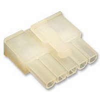
RECEPTACLE HOUSING, 5WAY
Manufacturer
TE Connectivity
Series
VAL-U-LOKr
Datasheet
1.1586022-4.pdf
(14 pages)
Specifications of 1586026-5
Pitch Spacing
4.2mm
No. Of Contacts
5
No. Of Rows
1
Connector Mounting
Free
Gender
Receptacle
Contact Material
Brass
Contact Plating
Tin
Colour
Clear
Rohs Compliant
Yes
Product Type
Connector
Connector Type
Housing
Termination Method To Wire/cable
Crimp
Sealed
No
Ul File Number
E28476
Csa File Number
208567
Mating Retention Type
Latching
Contact Current Rating, Max (a)
9
Operating Voltage Reference
AC
Operating Voltage (vac)
600
Profile Height (y-axis) (mm [in])
7.50 [0.295]
Number Of Positions
5
Number Of Rows
1
Centerline (mm [in])
4.20 [0.165]
Mating Retention
With
Selectively Loaded
No
Length (x-axis) (mm [in])
22.20 [0.874]
Width (z-axis) (mm [in])
19.80 [0.779]
Contact Type
Socket
Contact Design
Dual Beam
Connector Style
Receptacle
Mating Alignment
With
Mating Alignment Type
Keyed
Housing Color
Natural
Ul Flammability Rating
UL 94V-2
Rohs/elv Compliance
RoHS compliant, ELV compliant
Lead Free Solder Processes
Not relevant for lead free process
Rohs/elv Compliance History
Always was RoHS compliant
Agency/standard
UL, CSA
Ul Rating
Recognized
Circuit Identification Feature
With
Operating Temperature (°c [°f])
-40 – +105 [-40 – +221]
Applies To
Wire/Cable
Application Use
Wire-to-Board, Wire-to-Board / Wire-to-Wire, Wire-to-Wire
Contact Transmits (typical Application)
Signal (Data)
Pick And Place Cover
Without
Packaging Method
Bag
Available stocks
Company
Part Number
Manufacturer
Quantity
Price
Company:

Part Number:
1586026-5
Manufacturer:
TE Connectivity AMP Connectors
Quantity:
549


3.12. PC Board Solder Tine Holes
The holes in the pc board for the solder tines must be drilled and plated through to specific dimensions. See
Figure 10.
3.13. PC Board Header Assembly Placement
3.14. Soldering
Rev K
CAUTION
NOTE
Type RMA (Mildly Activated)
A. Manual Placement
Align the header assembly solder tines with the appropriate holes in the pc board. Start all solder tines into
the board, then press on the header until it seats on the pc board.
B. Robotic Placement
The robotic equipment must be adjusted to feed, pick up, and place the headers on the pc board with an
accuracy of 0.25 mm. The header assembly datum surfaces detailed on the customer drawing will ensure
correct placement of the header. For information on robotic equipment, see Section 5, TOOLING.
A. Flux Selection
Contact solder tines must be fluxed prior to soldering with a mildly active, rosin base flux. Selection of the
flux will depend on the type of pc board and other components mounted on the board. Additionally, the flux
must be compatible with the wave solder line, manufacturing, health, and safety requirements. Call the
Product Information phone number at the bottom of page 1 for consideration of other types of flux. Some
fluxes that are compatible with these header assemblies are provided in Figure 11.
B. Soldering Guidelines
VAL--U--LOK Series Header Assemblies can be soldered using a variety of soldering techniques. The
temperatures and exposure time shall be within the ranges specified in Figure 12. We recommend using
SN60 or SN62 solder for these header assemblies.
!
i
FLUX TYPE
FLUX TYPE
The header assemblies should be handled only by the housing to prevent deformation or other damage to the solder
tines.
Manual 402- - 40 provides some guidelines for establishing soldering practices. Refer to Paragraph 2.4, Manuals.
KESTER AND ALPHA are trademarks of their respective owners.
Dia of Finished Hole After
Plating (Vertical 1.28 +0.1)
(Right- - Angle 1.8 +0.1)
Board Thickness
1.78 Max
Tin/Lead Plated
(As Required)
(As Required)
Drilled Hole Diameter
ACTIVITY
ACTIVITY
Mild
Figure 10
Figure 11
Noncorrosive
RESIDUE
RESIDUE
KESTER
Pad Diameter
(As Required)
COMMERCIAL DESIGNATION
Copper Plating
(As Required)
(Maximum Hardness
of Copper to be 150
Knoop)
186
ALPHA
611
114- 13172
9 of 14
Related parts for 1586026-5
Image
Part Number
Description
Manufacturer
Datasheet
Request
R

Part Number:
Description:
Printers THERMAL PRINTER HS-SLEEVE MARKER
Manufacturer:
TE Connectivity


Part Number:
Description:
Manufacturer:
TE Connectivity
Datasheet: