1586026-5 TE Connectivity, 1586026-5 Datasheet - Page 5
1586026-5
Manufacturer Part Number
1586026-5
Description
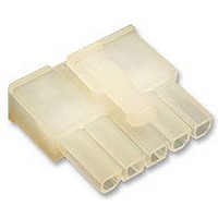
RECEPTACLE HOUSING, 5WAY
Manufacturer
TE Connectivity
Series
VAL-U-LOKr
Datasheet
1.1586022-4.pdf
(14 pages)
Specifications of 1586026-5
Pitch Spacing
4.2mm
No. Of Contacts
5
No. Of Rows
1
Connector Mounting
Free
Gender
Receptacle
Contact Material
Brass
Contact Plating
Tin
Colour
Clear
Rohs Compliant
Yes
Product Type
Connector
Connector Type
Housing
Termination Method To Wire/cable
Crimp
Sealed
No
Ul File Number
E28476
Csa File Number
208567
Mating Retention Type
Latching
Contact Current Rating, Max (a)
9
Operating Voltage Reference
AC
Operating Voltage (vac)
600
Profile Height (y-axis) (mm [in])
7.50 [0.295]
Number Of Positions
5
Number Of Rows
1
Centerline (mm [in])
4.20 [0.165]
Mating Retention
With
Selectively Loaded
No
Length (x-axis) (mm [in])
22.20 [0.874]
Width (z-axis) (mm [in])
19.80 [0.779]
Contact Type
Socket
Contact Design
Dual Beam
Connector Style
Receptacle
Mating Alignment
With
Mating Alignment Type
Keyed
Housing Color
Natural
Ul Flammability Rating
UL 94V-2
Rohs/elv Compliance
RoHS compliant, ELV compliant
Lead Free Solder Processes
Not relevant for lead free process
Rohs/elv Compliance History
Always was RoHS compliant
Agency/standard
UL, CSA
Ul Rating
Recognized
Circuit Identification Feature
With
Operating Temperature (°c [°f])
-40 – +105 [-40 – +221]
Applies To
Wire/Cable
Application Use
Wire-to-Board, Wire-to-Board / Wire-to-Wire, Wire-to-Wire
Contact Transmits (typical Application)
Signal (Data)
Pick And Place Cover
Without
Packaging Method
Bag
Available stocks
Company
Part Number
Manufacturer
Quantity
Price
Company:

Part Number:
1586026-5
Manufacturer:
TE Connectivity AMP Connectors
Quantity:
549


3.5. Placement of Crimped Contact in Housing
The contact must be inserted in the back of the housing and snapped into place. Install the contact so the wire
barrel is facing the housing latch. When fully inserted, the locking lances will engage the housing and prevent
backing out during mating of the connector. After inserting contact into housing, pull back lightly on the wire to
ensure contact is fully seated. See Figure 5.
Rev K
NOTE
B. Straightness
The force applied during crimping may cause some bending between the crimped wire barrel and the
mating portion of the contact. Such deformation is acceptable within the following limits.
i
6. Conductor/Insulation
The conductor and insulation must both be visible in the area between the insulation barrel and the wire
barrel.
7. Bellmouth
The front and rear bellmouths are caused by the extrusion of metal during crimping and must be within
the range specified in Figure 3.
8. Cutoff Tab and Burr
The cutoff tab and burr resulting from the contact being cut from the carrier strip must be within limits to
allow the contact to be fully inserted and seated in the housing. See Figure 3.
9. Flash
The wire barrel flash at the bottom of the wire barrel results from applied crimp pressure and must be
within the dimension provided in Section X--X of Figure 3.
10. Twist and Roll
There shall be no twist, roll, deformation, or other damage to the mating portion of the crimped contact
that will prevent proper mating. See Figure 3.
1. Up and Down
The crimped contact, including cutoff tab and burr, shall not be bent above or below the datum line more
than the amount shown in Figure 4.
2. Side to Side
The side--to--side bending of the contact may not exceed the limits provided in Figure 4.
Periodic inspections must be made to ensure crimped contact formation is consistent as referenced.
Figure 4
Datum Line
3_ Max
3_ Max
3_ Max
3_ Max
114- 13172
5 of 14
Related parts for 1586026-5
Image
Part Number
Description
Manufacturer
Datasheet
Request
R

Part Number:
Description:
Printers THERMAL PRINTER HS-SLEEVE MARKER
Manufacturer:
TE Connectivity


Part Number:
Description:
Manufacturer:
TE Connectivity
Datasheet: