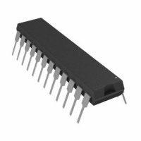
AD7870JNZ Analog Devices Inc, AD7870JNZ Datasheet - Page 18

AD7870JNZ
Manufacturer Part Number
AD7870JNZ
Description
IC ADC 12BIT LC2MOS 100KHZ 24DIP
Manufacturer
Analog Devices Inc
Datasheet
1.AD7870JNZ.pdf
(28 pages)
Specifications of AD7870JNZ
Data Interface
Serial, Parallel
Number Of Bits
12
Sampling Rate (per Second)
100k
Number Of Converters
1
Power Dissipation (max)
95mW
Voltage Supply Source
Dual ±
Operating Temperature
0°C ~ 70°C
Mounting Type
Through Hole
Package / Case
24-DIP (0.300", 7.62mm)
Resolution (bits)
12bit
Sampling Rate
100kSPS
Input Channel Type
Single Ended
Supply Voltage Range - Analog
± 4.75V To ± 5.25V
Supply Current
8mA
Number Of Elements
1
Resolution
12Bit
Architecture
SAR
Sample Rate
100KSPS
Input Polarity
Bipolar
Input Type
Voltage
Rated Input Volt
±3V
Differential Input
No
Power Supply Requirement
Dual
Single Supply Voltage (typ)
Not RequiredV
Single Supply Voltage (min)
Not RequiredV
Single Supply Voltage (max)
Not RequiredV
Dual Supply Voltage (typ)
±5V
Dual Supply Voltage (min)
±4.75V
Dual Supply Voltage (max)
±5.25V
Power Dissipation
95mW
Integral Nonlinearity Error
±0.5LSB(Typ)
Operating Temp Range
0C to 70C
Operating Temperature Classification
Commercial
Mounting
Through Hole
Pin Count
24
Package Type
PDIP
Input Signal Type
Single-Ended
Lead Free Status / RoHS Status
Lead free / RoHS Compliant
Lead Free Status / RoHS Status
Lead free / RoHS Compliant, Lead free / RoHS Compliant
AD7870/AD7875/AD7876
AC Linearity Plot
When a sine wave of specified frequency is applied to the V
input of the AD7870/AD7875 and several million samples are
taken, a histogram showing the frequency of occurrence of each
of the 4096 ADC codes can be generated. From this histogram
data it is possible to generate an ac integral linearity plot as
shown in Figure 21. This shows very good integral linearity
performance from the AD7870/AD7875 at an input frequency
of 25 kHz. The absence of large spikes in the plot shows good
differential linearity. Simplified versions of the formulae used
are outlined below.
where:
INL(i) is the integral linearity at code i.
V(fs) and V(o) are the estimated full-scale and offset transitions.
V(i) is the estimated transition for the i
INL
–120
–30
–60
–90
0
( )
i
0
=
⎡
⎢
⎢
⎣
V
V
( )
( )
fs
i
−
−
V
V
Figure 20. IMD Plot
( )
( )
o
INPUT FREQUENCIES
SAMPLING FREQUENCY = 100kHz
IMD
o
F1 = 9.05kHz
F2 = 9.55kHz
T
ALL TERMS = 90.06dB
SECOND ORDER TERMS = 92.73dB
THIRD ORDER TERSM = 93.45dB
FREQUENCY (kHz)
A
= 25°C
×
4096
⎤
⎥
⎥
⎦
−
th
i
code.
5
0
IN
Rev. C | Page 18 of 28
V(i), the estimated code transition point, is derived as follows:
where:
A is the peak signal amplitude.
N is the number of histogram samples.
cum(i) =
V
–0.25
–0.50
0.25
( )
0.5
i
0
∑
=
0
−
i
n
A
=
0
511
×
V
Cos
( )
n
1023
[
π
Figure 21. AC INL Plot
occurrences.
×
cum
N
1535
( )
i
CODE
INPUT FREQUENCY = 25kHz
SAMPLE FREQUENCY = 100kHz
T
2047
]
A
= 25°C
2559
3071
3583
4095


