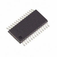
MAXQ3180-RAN+ Maxim Integrated Products, MAXQ3180-RAN+ Datasheet - Page 72

MAXQ3180-RAN+
Manufacturer Part Number
MAXQ3180-RAN+
Description
IC AFE POLYPHASE MULTI 28-TSSOP
Manufacturer
Maxim Integrated Products
Datasheet
1.MAXQ3180-RAN.pdf
(101 pages)
Specifications of MAXQ3180-RAN+
Number Of Channels
8
Power (watts)
35mW
Voltage - Supply, Analog
3.6V
Voltage - Supply, Digital
3.6V
Package / Case
28-TSSOP
For Use With
MAXQ3180-KIT - KIT EV REFRNC DSIGN FOR MAXQ3180
Lead Free Status / RoHS Status
Lead free / RoHS Compliant
Number Of Bits
-
Low-Power, Multifunction, Polyphase AFE
The current channel includes a variable-gain amplifier
that introduces a gain of 32 when the current falls
below the low current threshold (about 1/32 of full-scale
current I
be controlled with arbitrary precision, and because
high gain implies increased noise, it may be necessary
to calibrate the MAXQ3180 to maintain linearity at the
lowest inputs.
There are two settings that manage low-current lineari-
ty: an offset setting, OFFS_LO; and a gain setting,
GAIN_LO. Setting the offset is simple. Ensure no cur-
rent is flowing in the current circuit. Read X.IRMS. To
calculate offset use following formula:
If LINFRM = 0:
If LINFRM = 1:
Program the offs into the OFFS_LO register.
So, if the user reads 0x0113 from the X.IRMS register and
LINFRM = 1, program 0xFEED into the OFFS_LO register.
Setting the GAIN_LO register means applying a current
below the low-current threshold, reading the value from
the MAXQ3180, and adjusting the gain accordingly. Note
that, unlike offset, the low-end gain is added to the overall
gain provided in the I_GAIN register.
Apply a known current with peak value less than the
low-current threshold. Ensure that there is no previous
value in the low-current gain register, A.GAIN_LO, by
setting this register to 0x4000. Read the A.IRMS regis-
ter (0x1CC). Note the value. Convert the known value to
meter units by multiplying the known value (in amperes)
by 2
culation by the value read from the MAXQ3180. The
result should be a value between 0 and 2. Convert the
integer by multiplying 2
result is the gain value to be programmed into
A.GAIN_LO.
Once voltage and current have been calibrated, the
energy and power calculation automatically reflects the
calibrated voltage and current. However the energy
gain factor (X.E_GAIN, X = A/B/C) can be further tuned
to achieve even more accurate power and energy
result if necessary. For example, if the voltage and cur-
rent calibration sources are not as accurate as the
power/energy calibration source, then the additional
gain calibration may be necessary. The following pro-
72
24
______________________________________________________________________________________
and dividing by I
FS
). Because the gain of the amplifier cannot
offs
offs = -X.IRMS
Calibrating Power/Energy Gain
= −
14
FS
, and ensure MSB is zero. The
. Divide the results of this cal-
( .
X IRMS
2
16
Calibrating Linearity
)
2
cedure for power/energy gain calibration is outlined for
phase A.
• Apply a precision unity power factor power (applied
• Read the PWRP.A register. Note the value.
• Convert the applied value to meter units by dividing it
• Divide the applied value (in meter unit) by the value
• Multiply the calculated value by 2
• When the gain value is programmed, wait for 1 to 2
To perform the calibration at three current levels, note
the raw current value (X.IRMS) at each point. Label the
current values, from highest to lowest, I
Program X.PA0, X.PA1, and X.PA2 with the phase offset
values calculated at I
described in the Calibrating Phase Offset section.
Finally, program I1THR with the average of I
and program I2THR with the geometric average of I
and I
adjusted accordingly. See Figure 16.
Figure 16. Phase Offset vs. Input Current Calibration
value) that is close to the desired normal operating
point.
by MU_PWR.
read from the MAXQ3180. The result should be a
value between 0 and 2. If the value falls outside of
this range, I
calculated.
MSB is zero. The result is the gain value to be pro-
grammed into A.E_GAIN.
seconds, then reread the power value from PWRP.A.
Check that the measured value is correct by compar-
ing PWRP.A against the applied power in meter unit.
2
. Now as the current changes the phase offset is
2
1
0
I
2
FS
and/or V
Multipoint Phase Offset Calibration
PA2
PA1
I2THR
0
, I
INPUT CURRENT
FS
1
I
, and I
1
have probably been mis-
I1THR
2
14
, respectively, as
, and ensure the
0
I
0
, I
PA0
1
0
, and I
and I
2
1
1
.
,


