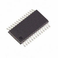
MAXQ3180-RAN+ Maxim Integrated Products, MAXQ3180-RAN+ Datasheet - Page 23

MAXQ3180-RAN+
Manufacturer Part Number
MAXQ3180-RAN+
Description
IC AFE POLYPHASE MULTI 28-TSSOP
Manufacturer
Maxim Integrated Products
Datasheet
1.MAXQ3180-RAN.pdf
(101 pages)
Specifications of MAXQ3180-RAN+
Number Of Channels
8
Power (watts)
35mW
Voltage - Supply, Analog
3.6V
Voltage - Supply, Digital
3.6V
Package / Case
28-TSSOP
For Use With
MAXQ3180-KIT - KIT EV REFRNC DSIGN FOR MAXQ3180
Lead Free Status / RoHS Status
Lead free / RoHS Compliant
Number Of Bits
-
example, if synchronization is lost), the host only needs
to wait for the SPI to time out before restarting commu-
nication from the first command byte. SPI timeout count
starts after receiving the first command byte from the
master (after the 8th SPI clock of the first byte). The
count stops and clears after receiving the last byte of a
transaction (after the 8th SPI clock of the last byte).
If the timeout count expires (exceeds COM_TIMO)
before the transaction completes, the MAXQ3180 aban-
dons the unfinished transaction and resets the SPI logic
to be ready for the next transaction. The default SPI
timeout is 320ms.
Optionally, a CRC byte can be appended to each
transaction. For write commands, the CRC byte is sent
by the master, and for read commands the CRC byte is
Table 2. Command Format for SPI Register Write
(Last data byte)
(1st data byte)
(N + 1) byte
Sync bytes
2nd byte
Nth byte
1st byte
3rd byte
BYTE
...
Low-Power, Multifunction, Polyphase AFE
______________________________________________________________________________________
Master sends command;
Slave sends 0xC1 byte
Master sends address;
Slave sends 0xC2 byte
Master sends data;
Slave sends ACK (0x41)
Master sends data;
Slave sends ACK (0x41)
Master sends CRC;
Slave sends ACK (0x41)
Master sends dummy;
Slave sends ACK (0x41) or
NACK (0x4E) byte
TRANSFERS
...
BIT
7:6
5:4
3:0
7:0
7:0
7:0
7:0
7:0
...
Command code:
Data Length:
MSB portion of data address.
LSB portion of data address.
Data, LSB
Data, MSB
Optional CRC
Master sends dummy byte; Slave responds with NACK if busy,
or with ACK when processing complete.
Master must receive ACK before starting the next transaction.
00 Read
01 Reserved
10 Write
11 Reserved
00 1 Byte
01 2 Bytes
10 4 Bytes
11 8 Bytes
sent by the MAXQ3180. The CRC mode is enabled
when the CRCEN bit is set to 1 in OPMODE1 register.
Otherwise, the MAXQ3180 assumes no CRC byte is
used. The 8-bit CRC is calculated for all bytes in a
transaction, from the first command byte sent by the
master through the last data byte excluding sync bytes,
using the polynomial P = x
mitted CRC byte does not match the calculated CRC
byte (for a write command), the MAXQ3180 ignores the
command.
The length of the transfer is defined by the first com-
mand byte and the status of the CRCEN bit in the
OPMODE1 register. There is no special synchronization
mechanism provided in this simple protocol. Therefore,
the master is responsible for sending/receiving the cor-
rect number of bytes. If the master mistakenly sends
DESCRIPTION
...
8
+ x
5
+ x
4
+ 1. If the trans-
23


