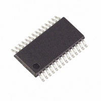
MAXQ3180-RAN+ Maxim Integrated Products, MAXQ3180-RAN+ Datasheet - Page 63

MAXQ3180-RAN+
Manufacturer Part Number
MAXQ3180-RAN+
Description
IC AFE POLYPHASE MULTI 28-TSSOP
Manufacturer
Maxim Integrated Products
Datasheet
1.MAXQ3180-RAN.pdf
(101 pages)
Specifications of MAXQ3180-RAN+
Number Of Channels
8
Power (watts)
35mW
Voltage - Supply, Analog
3.6V
Voltage - Supply, Digital
3.6V
Package / Case
28-TSSOP
For Use With
MAXQ3180-KIT - KIT EV REFRNC DSIGN FOR MAXQ3180
Lead Free Status / RoHS Status
Lead free / RoHS Compliant
Number Of Bits
-
EOVF: Energy overflow. This flag indicates that one or
more energy accumulators (X.EAPOS, X.EANEG, etc.)
have overflowed. In a traditional meter, the host
processor would poll the MAXQ3180 to determine
which of the energy accumulators have overflowed and
adjust its internal accounting registers accordingly.
OC: The RMS current value on one or more of the
phases over the most recent DSP cycle has exceed-
ed the value set in the OCLVL register.
OV: The RMS voltage on one or more of the phases
over the most recent DSP cycle has exceeded the
value set in the OVLVL register.
UV: The RMS voltage on one or more of the phases
over the most recent DSP cycle has failed to exceed
the value set in the UVLVL register.
NOZX: Zero crossings were not detected on one or
more of the phases. The detection time is defined in
the NZX_TIMO register. The resolution for the
NZX_TIMO register is the duration of one ADC sam-
ple time (nominally 40μs).
DCHA: Tells the host processor that the direction of
net real energy flow on one of the three phases has
changed during the current DSP cycle as compared
to the previous DSP cycle.
DCHR: Tells the host processor that the direction of
net reactive energy flow on one of the three phases
has changed during the current DSP cycle as com-
pared to the previous DSP cycle.
DSPRDY: Indicates the latest DSP cycle has just
completed.
DSPOR: Indicates that the processing for the previ-
ous DSP cycle had not been completed before the
current DSP cycle became available for processing.
This overflow indication should never be seen in the
default configuration; however, under some condi-
tions (faster ADC rate, slower CPU clock) the pro-
cessing requirements may exceed the number of
CPU cycles available for DSP processing. Under
these circumstances, the clock rate may be
increased, the ADC rate may be reduced (that is,
the R_ADCRATE register may be increased), or the
functional load (such as fundamental mode calcula-
tions) may be cut.
Note that when DSPOR becomes set, all DSP calcu-
lations as well as all pulse outputs are invalidated.
The appropriate host response is to take the remedi-
al action described above and discard the current
set of DSP result values.
Low-Power, Multifunction, Polyphase AFE
______________________________________________________________________________________
Each phase has a local register that contains copies of
the OC, OV, UV, NOZX, DCHA, and DCHR bits. Thus,
to determine which phase(s) have exception conditions
requires four reads: the IRQ_FLAG register to deter-
mine which conditions are active that are causing the
interrupt to occur, and then a read to A.FLAGS,
B.FLAGS, and C.FLAGS to determine which of the
phases have the indicated condition.
Finally, each phase has a pair of local registers that
contain overflow flags for each energy accumulator. If
the EOVF bit is set in the IRQ_FLAG register, the host
should then read the A.EOVER, B.EOVER, and
C.EOVER registers to determine which of the phases
have overflow conditions. If fundamental mode opera-
tion is enabled, the host should read A.EFOVER,
B.EFOVER, and C.EFOVER as well. Each of these reg-
isters contains a bit for each of real and reactive energy
in both positive and negative direction as well as
apparent energy.
The MAXQ3180 detects overvoltage and overcurrent
events and can issue interrupt request signals to the
master when these events occur. The overvoltage level
can be programmed into the OVLVL register, while the
overcurrent level is determined by the OCLVL register.
Both OVLVL and OCLVL registers represent the bits
23:8 of the VRMS or IRMS registers. Any time the
MAXQ3180 detects the RMS-value exceeding a thresh-
old level, the OV or OC interrupt flag is set. If enabled,
any of these flags issues an interrupt request. All inter-
rupt flags are “sticky” bits—the MAXQ3180 never
clears them on its own unless a reset occurs. The inter-
rupt flags should be cleared by the master by writing
the appropriate register.
All energy calculations, including various threshold
checks, are performed internally in fixed format in meter
units. Therefore, the threshold values must be supplied
by the user in meter units as well. This section summa-
rizes how to convert real units (V, A, kWh, W, and kAh)
into meter units and vice versa.
The conversion factors are based on the settings of t
V
t
defined by the R_ADCRATE setting and system clock
frequency f
Default conditions are R_ADCRATE = 319, f
FR
FS
, and I
is analog scan frame timing. This parameter is
Meter Units to Real Units Conversion
FS
SYS
t
, defined by the user’s design.
FR
Overvoltage and Overcurrent Detection
:
= (R_ADCRATE + 1) x 8/f
SYS
SYS
= 8MHz.
FR
63
,


