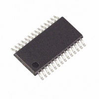
MAXQ3181-RAN+ Maxim Integrated Products, MAXQ3181-RAN+ Datasheet - Page 61

MAXQ3181-RAN+
Manufacturer Part Number
MAXQ3181-RAN+
Description
IC AFE POLYPHASE LO-PWR 28-TSSOP
Manufacturer
Maxim Integrated Products
Datasheet
1.MAXQ3181-RAN.pdf
(84 pages)
Specifications of MAXQ3181-RAN+
Number Of Channels
8
Power (watts)
35mW
Voltage - Supply, Analog
3.3V
Voltage - Supply, Digital
3.3V
Package / Case
28-TSSOP
Lead Free Status / RoHS Status
Lead free / RoHS Compliant
Number Of Bits
-
Generally, three-phase power as delivered from the util-
ity consists of four wires: three voltage phases and a
neutral wire. In one typical three-phase delivery system,
measuring from neutral to any phase would read 120V,
while measuring from any phase to any other phase
would read 208V. Connecting a load so that load cur-
rent is taken from phase lines and returned to neutral is
called a wye-connected load. Connecting a load so
that load current is provided by one phase and
returned on another phase is called a delta-connected
load. The MAXQ3181 can measure power consumed in
either a wye-connected or a delta-connected load.
If the load is connected in a wye fashion, the voltage is
measured from the neutral lead to each of the phases,
and the current measuring device is placed in series
with the load, most often in the hot lead. The sensor is
not placed in the neutral lead to prevent a customer
from defrauding the utility by returning the current to
ground rather than neutral. A current sensor placed in
the hot lead makes fraud even more difficult.
A delta-connected load can have current measured in
two possible ways. If it is primarily desirable to know
how much power is delivered to the load, one can place
the current sensor in the load circuit between two phas-
es. But if it is more important to know how much current
is being drawn from each supply phase, each current
sensor is placed in the line circuit of each single phase.
Most utilities are only concerned with the total amount
of energy being consumed. If individually accounting
for the power delivered by each phase is not a require-
ment, it is not necessary to measure all three voltages.
Instead, knowing only two voltages and the three cur-
rents is all that is necessary to measure total energy
usage.
There are several ways of doing this. In a wye arrange-
ment, one of the phases—usually phase B—–can be
considered the voltage reference point instead of neu-
tral. Then the voltage measurements can be made from
phase A to phase B and from phase C to phase B. By
using some simple arithmetic, the power delivered by
phase A, phase B, and phase C can be calculated
even though only two voltages are available.
A second mechanism is to have a delta-connected
load, but with one leg—usually the BC leg—split into
two equal loads. The point where the load is split is
defined as the reference. In this arrangement, it is only
necessary to know the voltage between phase C and
the split and phase A and the split, since V
Connections to the Power Source
Low-Power, Active Energy, Polyphase AFE
______________________________________________________________________________________
C
= -V
A
.
Finally, there is the connection arrangement in which
the load is in a delta configuration with the current sen-
sor at each load, but it is still desired to determine how
much current is in each supply branch. The MAXQ3181
supports all of these connection arrangements.
The MAXQ3181 supports a variety of voltage and cur-
rent sense elements. This section describes the proper-
ties of many of these sensing devices.
A voltage-divider is an ideal voltage-sensing element
when there is no need for voltage isolation. Modern
resistors have virtually no parasitic capacitance or
inductance at the frequencies of interest in an electrici-
ty meter and have extremely low variation with tempera-
ture. When selecting resistors for a voltage-divider,
keep the division ratio high enough so that the peak
voltage value cannot exceed the maximum allowable
input voltage. In the MAXQ3181, the peak input voltage
is about 1V; consequently, a divider in the range of
400:1 to 600:1 is ideal.
The second consideration is the total power dissipation
and voltage hold-off requirements of the resistor. It is
tempting to design a 400:1 divider with a 400kΩ resis-
tor in series with a 1kΩ resistor, but that would force the
400kΩ resistor to dissipate about 140mW. This is not an
excessive amount of power, but if the design is to use
small SMT parts, it can handle greater than a 1/10W
SMT resistor. It is better to use a series of several small-
er components to improve system reliability.
If isolation is required between the meter electronics
and the line, a voltage transformer is required. A volt-
age transformer is designed to faithfully transfer an AC
voltage applied on the primary side to a sensor on the
secondary side. On the primary side, a voltage-divider
is used to reduce the voltage to a workable level. On
the secondary side, a load resistor is selected so that
the current in the transformer windings is safely within
the transformer’s linear operating region.
Because the impedance seen in the primary side of the
transformer is equal to the impedance of the load resis-
tor in the secondary circuit plus impedance of the
transformer secondary winding at the operating fre-
quency, it is easy to calculate the value of the required
voltage-divider resistors in the primary side. For exam-
ple, assume we want a 500:1 divider ratio and assume
Sensor Selection
Voltage Transformer
Voltage Sensors
Voltage-Divider
61


