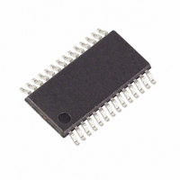
MAXQ3181-RAN+ Maxim Integrated Products, MAXQ3181-RAN+ Datasheet - Page 52

MAXQ3181-RAN+
Manufacturer Part Number
MAXQ3181-RAN+
Description
IC AFE POLYPHASE LO-PWR 28-TSSOP
Manufacturer
Maxim Integrated Products
Datasheet
1.MAXQ3181-RAN.pdf
(84 pages)
Specifications of MAXQ3181-RAN+
Number Of Channels
8
Power (watts)
35mW
Voltage - Supply, Analog
3.3V
Voltage - Supply, Digital
3.3V
Package / Case
28-TSSOP
Lead Free Status / RoHS Status
Lead free / RoHS Compliant
Number Of Bits
-
Low-Power, Active Energy, Polyphase AFE
tents of I1THR, then the angle expressed in PA0 is used
to compensate the phase angle. If the raw RMS current
is less than I2THR, then the angle expressed in PA2 is
used to compensate the phase angle. And if the raw
RMS current falls between I1THR and I2THR then PA1 is
used to compensate the phase angle. In this way, a
three-piece stepwise approximation of the phase
response of the current sensor is available.
To use a constant phase compensation, set I1THR and
I2THR to zero and insert the phase compensation value
into PA0.
Apparent energy is calculated as the product of the raw
RMS volts and amps.
Line Frequency: Line frequency can be taken directly
from the NS value. Recall that NS is the number of
frames in a DSP cycle. Since each frame is 320μs, sim-
ply multiply NS by 320μs and divide by CYCNT to
obtain the line period. The reciprocal of this is the line
frequency.
Once real energy over the most recent DSP cycle has
been calculated, it is necessary to accumulate the
result.
The result accumulated during any DSP cycle can be
positive (that is, energy is delivered to the load) or neg-
Figure 11. Phase Compensation for Energy Calculations
Figure 12. Apparent Energy Calculations
52
______________________________________________________________________________________
PA
=
⎧
⎪
⎨
⎪
⎩
PA
PA I THR I
PA
E
P
1 1
0
2
,
,
, , I
I
RMS
RMS
≥
>
<
Energy Accumulation
I THR
I THR
1
2
RMS
RAW_V
RAW_I
≥
COMPENSATION
I THR
2
PHASE
PA0
PA1
PA2
)
⎫
⎪
⎬
⎪
⎭
X × Y
LINEARIZATION
APPSEL = 0
GAIN_LO
OFFS_LO
OFFS_HI
E_GAIN
ative (that is, energy is driven back into the line). These
values are separately accumulated.
Apparent energy is also accumulated, but since this
value is always positive or zero, there is only one
apparent energy accumulator.
From time to time, the accumulators generate an over-
flow. When this occurs, the appropriate bit is set in the
overflow status register X.EOVER.
When an overflow occurs, supervisory code running on
the host processor must make the appropriate adjust-
ments in the reported energy. In many cases, this could
simply involve incrementing an overflow counter. The
host processor must then clear the overflow indication.
The MAXQ3181 monitors the voltage signal on each
phase for zero-crossing events. If no ascending zero
crossings are detected within a specified number
(NZX_TIMO) of analog scan sample periods, the
NOZXF (X.FLAGS) flag is set by the MAXQ3181 to noti-
fy the master of this condition. If the NOZXM bit is set,
this flag sets the NOZX bit in the IRQ_FLAG. If the inter-
rupt enable bit ENOZX is set to 1, the interrupt signal
IRQ is driven low by the MAXQ3181 whenever NOZX =
1. The master can clear NOZXF and NOZX back to 0 to
remove the interrupt condition.
A phase sequence status bit PHSEQ indicates the
order in which zero crossings are detected. When a
zero-crossing event occurs on the phase A voltage sig-
nal, followed by phase B, phase C, and then phase A
AVERAGE
AVG_C
E_GAIN
E
APPARENT
AVERAGE
AVG_C
No-Zero-Crossing Detection
Phase Sequence Status
E
E_RAW
REAL
REAL


