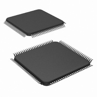
LM9833CCVJD/NOPB National Semiconductor, LM9833CCVJD/NOPB Datasheet - Page 15

LM9833CCVJD/NOPB
Manufacturer Part Number
LM9833CCVJD/NOPB
Description
IC USB IMAGE SCAN 48BIT 100-TOFP
Manufacturer
National Semiconductor
Datasheet
1.LM9833CCVJDNOPB.pdf
(42 pages)
Specifications of LM9833CCVJD/NOPB
Number Of Bits
16
Number Of Channels
3
Voltage - Supply, Analog
5V
Voltage - Supply, Digital
4.5 V ~ 5.5 V
Package / Case
100-TQFP, 100-VQFP
Lead Free Status / RoHS Status
Lead free / RoHS Compliant
Power (watts)
-
Other names
*LM9833CCVJD
*LM9833CCVJD/NOPB
LM9833CCVJD
*LM9833CCVJD/NOPB
LM9833CCVJD
Register Listing
Address
ILLUMINATION SETTINGS
STATIC OFFSET AND GAIN SETTINGS FOR ANALOG FRONT END
2A
2B
2C
2D
2E
2F
3A
3B
3C
3D
29
30
31
32
33
34
35
36
37
38
39
Illumination Mode
Controls the function of the 3 LAMP outputs:
LAMP
Mode 0 is the Off/Reset state.
Mode 1 is typically used for CCFL lamps.
Mode 2 is for color scanning with tri-color
LEDs.
Mode 3 is for grayscale scanning with tri-
color LEDs.
LAMP
LAMP
LAMP
LAMP
LAMP
LAMP
LAMP
LAMP
LAMP
LAMP
LAMP
LAMP
LAMP
LAMP
LAMP
Static Offset (Red)
Static Offset (Green)
Static Offset (Blue)
Static Gain (Red)
Static Gain (Green)
Static Gain (Blue)
R
B
G
G
R
R
R
R
G
G
G
G
B
B
B
B
, LAMP
for INT IME ADJ
On - MSB
On - LSB
Off - MSB
Off - LSB
On - MSB
On - LSB
Off - MSB
Off - LSB
PWM - MSB (Illumination Mode 1)
PWM - LSB (Illumination Mode 1)
On - MSB
On - LSB
Off - MSB
Off - LSB
G
(Continued)
, and LAMP
Function
B
D
n n n n n n n n
n n n n n n n n
n n n n n n n n
n n n n n n n n
n n n n n n n n
n n n n n n n n
n n n n n n n n
7
D
6
D
n n n n n n n pixels (1 - 16384)
n n n n n n n pixels (1 - 16384)
n n n n n n n pixels (1 - 16384)
n n n n n n n pixels (1 - 16384)
n n n n n n n pixels (1 - 16384)
n n n n n n n pixels (1 - 16384)
0 n n n n n Offset = +n*9.3mV, n = 0 to 31
1 n n n n n Offset = -n*9.3mV, n = 0 to 31
0 n n n n n Offset = +n*9.3mV, n = 0 to 31
1 n n n n n Offset = -n*9.3mV, n = 0 to 31
0 n n n n n Offset = +n*9.3mV, n = 0 to 31
1 n n n n n Offset = -n*9.3mV, n = 0 to 31
0 n n n n n Gain = 0.93 + 0.067*n (V/V), n = 0 to 31
1 n n n n n Gain = 3(0.93 + 0.067*n) (V/V), n = 0 to 31
0 n n n n n Gain = 0.93 + 0.067*n (V/V), n = 0 to 31
1 n n n n n Gain = 3(0.93 + 0.067*n) (V/V), n = 0 to 31
0 n n n n n Gain = 0.93 + 0.067*n (V/V), n = 0 to 31
1 n n n n n Gain = 3(0.93 + 0.067*n) (V/V), n = 0 to 31
5
D
4
15
D
n n n n LAMP
3
D
2
0
1
D
0 0
0 1
1 0
1 1
1
D
0
LAMP
(Power-On/Reset Default)
Illumination Mode 1 - LAMP
every line, with their on and off points controlled by
the Pixel Counter settings. LAMP
continuous PWM pulse stream. (Figure 20)
LAMP
all times by setting the LAMP Off or LAMP On settings
(registers 2C-37) greater than the Line End value
(registers 20 and 21).
Illumination Mode 2 - LAMP
sequentially at the line rate, with their on and off
points controlled by Pixel Counter settings. (Figure
21)
Illumination Mode 3 - LAMP
every line, with their on and off points controlled by
the Pixel Counter settings. (Figures 22 and 23)
LAMP
LAMP
time, low during long integration time.
n/4095. Frequency = 48Mhz/4096 = 11.7kHz
This selects the pixel count at which the LAMP
output goes high (if programmed)
This selects the pixel count at which the LAMP
output goes low (if programmed)
This selects the pixel count at which the LAMP
output goes high (if programmed)
This selects the pixel count at which the LAMP
output goes low (if programmed)
This selects the pixel count at which the LAMP
output goes high (if programmed)
This selects the pixel count at which the LAMP
output goes low (if programmed)
R
R
B
B
G
operates normally
output is enabled during short integration
= LAMP
and/or LAMP
output is a PWM pulse stream. Duty cycle is
G
= LAMP
B
may be set to stay on or off at
Value
B
R
R
R
= 0V
, LAMP
, LAMP
and LAMP
G
Output is
G
G
www.national.com
, LAMP
, LAMP
B
turn on
B
B
turn on
turn on
R
R
G
G
B
B


