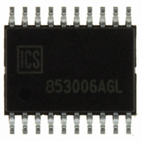
ICS853006AGLF IDT, Integrated Device Technology Inc, ICS853006AGLF Datasheet - Page 11

ICS853006AGLF
Manufacturer Part Number
ICS853006AGLF
Description
IC FANOUT BUFFER LVPECL 20-TSSOP
Manufacturer
IDT, Integrated Device Technology Inc
Series
HiPerClockS™r
Type
Fanout Buffer (Distribution)r
Specifications of ICS853006AGLF
Number Of Circuits
1
Ratio - Input:output
1:6
Differential - Input:output
Yes/Yes
Input
CML, LVDS, LVPECL, SSTL
Output
ECL, LVPECL
Frequency - Max
2GHz
Voltage - Supply
2.375 V ~ 3.465 V
Operating Temperature
-40°C ~ 85°C
Mounting Type
Surface Mount
Package / Case
20-TSSOP
Frequency-max
2GHz
Number Of Outputs
12
Operating Supply Voltage (max)
-3.465/3.465V
Operating Temp Range
-40C to 85C
Propagation Delay Time
0.51ns
Operating Supply Voltage (min)
-2.375/2.375V
Mounting
Surface Mount
Pin Count
20
Operating Supply Voltage (typ)
-2.5/-3.3/3.3V
Package Type
TSSOP
Operating Temperature Classification
Industrial
Lead Free Status / RoHS Status
Lead free / RoHS Compliant
Other names
800-1157
800-1157-5
800-1157
853006AGLF
800-1157-5
800-1157
853006AGLF
IDT™ / ICS™ LOW SKEW, 1-TO-6 DIFFERENTIAL-TO-2.5V/3.3V LVPECL/ECL FANOUT BUFFER
ICS853006
LOW SKEW, 1-TO-6 DIFFERENTIAL-TO-2.5V/3.3V LVPECL/ECL FANOUT BUFFER
S
Figure 5 shows a schematic example of ICS853006. The
ICS853006 input can accept various types of differential input
signal. In this example, the inputs are driven by an LVPECL driv-
ers. For the ICS853006 LVPECL output driver, an example of
LVPECL driver termination approach is shown in this schematic.
853006AG
CHEMATIC
E
3.3V
XAMPLE
Integrated
Circuit
Systems, Inc.
3.3V LVPECL
F
IGURE
Zo = 50
Zo = 50
C7(Optional)
5. ICS853006 LVPECL C
0.1u
R9
50
3.3V
D
IFFERENTIAL
R10
50
R11
50
www.icst.com/products/hiperclocks.html
10
1
2
3
4
5
6
7
8
9
U1
(U1, 1)
VCC
nQ0
Q0
nQ1
Q1
nQ2
Q2
VCC
PCLK
nPCLK
-
C1
0.1u
TO
3.3V
LOCK
ICS853006
11
-2.5V/3.3V LVPECL/ECL F
11
(U1, 8)
Additional LVPECL driver termination approaches are shown in
the LVPECL Termination Application Note. It is recommended
at least one decoupling capacitor per power pin. The decoupling
capacitors should be physically located near the power pins.
For ICS853006, the unused output can be left floating.
O
VCC
VCC
VEE
VBB
nQ5
nQ4
nQ3
Q5
Q4
Q3
UTPUT
C2
0.1u
20
19
18
17
16
15
14
13
12
11
(U1, 13)
B
3.3V
UFFER
C3
0.1u
(U1, 20)
S
CHEMATIC
Zo = 50
Zo = 50
Zo = 50
Zo = 50
C4
0.1u
E
XAMPLE
R2
50
R3
50
R5
50
R6
50
L
OW
R1
50
R4
50
C5 (Optional)
0.1u
C6 (Optional)
0.1u
+
-
+
-
ANOUT
REV. A NOVEMBER 9, 2004
S
KEW
, 1-
B
UFFER
TO
ICS853006
-6
TSD


