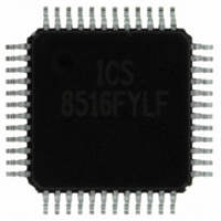
ICS8516FYLF IDT, Integrated Device Technology Inc, ICS8516FYLF Datasheet - Page 11

ICS8516FYLF
Manufacturer Part Number
ICS8516FYLF
Description
IC CLK DISTR 1:16 LVDS 48-LQFP
Manufacturer
IDT, Integrated Device Technology Inc
Series
HiPerClockS™r
Type
Fanout Buffer (Distribution)r
Datasheet
1.ICS8516FYLF.pdf
(16 pages)
Specifications of ICS8516FYLF
Number Of Circuits
1
Ratio - Input:output
1:16
Differential - Input:output
Yes/Yes
Input
HCSL, LVDS, LVHSTL, LVPECL, SSTL
Output
LVDS
Frequency - Max
700MHz
Voltage - Supply
3.135 V ~ 3.465 V
Operating Temperature
0°C ~ 70°C
Mounting Type
Surface Mount
Package / Case
48-LQFP
Frequency-max
700MHz
Number Of Outputs
32
Operating Supply Voltage (max)
3.465V
Operating Temp Range
0C to 70C
Propagation Delay Time
5ns
Operating Supply Voltage (min)
3.135V
Mounting
Surface Mount
Pin Count
48
Operating Supply Voltage (typ)
3.3V
Package Type
TQFP
Duty Cycle
55%
Operating Temperature Classification
Commercial
Lead Free Status / RoHS Status
Lead free / RoHS Compliant
Other names
800-1154
8516FYLF
8516FYLF
Available stocks
Company
Part Number
Manufacturer
Quantity
Price
Company:
Part Number:
ICS8516FYLF
Manufacturer:
AD
Quantity:
1 722
Company:
Part Number:
ICS8516FYLF
Manufacturer:
IDT, Integrated Device Technology Inc
Quantity:
10 000
Company:
Part Number:
ICS8516FYLFT
Manufacturer:
IDT, Integrated Device Technology Inc
Quantity:
10 000
IDT™ / ICS™ LOW SKEW, 1-TO-16 DIFFERENTIAL-TO-LVDS CLOCK DISTRIBUTION CHIP
ICS8516
LOW SKEW, 1-TO-16 DIFFERENTIAL-TO-LVDS CLOCK DISTRIBUTION CHIP
LVDS D
A general LVDS interface is shown in Figure 3. In a 100Ω
differential transmission line environment, LVDS drivers re-
quire a matched load termination of 100Ω across near the
8516FY
S
Figure 4 shows a schematic example of ICS8516. In this ex-
ample, the input is driven by an LVDS driver. For LVDS buffer,
it is recommended to terminate the unused outputs for better
CHEMATIC
RIVER
E
XAMPLE
Integrated
Circuit
Systems, Inc.
T
ERMINATION
LVDS_Driver
(U1-1)
3.3V
C1
0.1u
VDD=3.3V
LVDS_Driver
Zo = 50 Ohm
Zo = 50 Ohm
(U1-6)
R17
100
Decoupling capacitors located near the power pins
F
C2
0.1u
IGURE
(U1-12)
www.icst.com/products/hiperclocks.html
4. ICS8516 LVDS B
F
IGURE
C3
0.1u
13
14
15
16
17
18
19
20
21
22
23
24
(U1-25)
3. T
nQ1
Q1
nQ0
Q0
GND
nCLK
CLK
GND
Q15
nQ15
Q14
nQ14
Zo = 50 Ohm
Zo = 50 Ohm
D
C4
0.1u
YPICAL
VDD=3.3V
IFFERENTIAL
(U1-31)
11
LVDS D
11
C5
0.1u
receiver input. For a multiple LVDS outputs buffer, if only par-
tial outputs are used, it is recommended to terminate the un-
used outputs.
UFFER
signal integrity. The decoupling capacitors should be physi-
cally located near the power pin.
(U1-36)
GND
GND
nQ6
nQ7
OE1
OE2
nQ8
nQ9
Q6
Q7
Q8
Q9
S
RIVER
C6
0.1u
CHEMATIC
U1
8516
48
47
46
45
44
43
42
41
40
39
38
37
-
TO
T
R1
100
-LVDS C
ERMINATION
E
XAMPLE
Zo = 50 Ohm
Zo = 50 Ohm
Zo = 50 Ohm
Zo = 50 Ohm
Zo = 50 Ohm
Zo = 50 Ohm
R1
100
R16
100
R10
100
LOCK
CLK
nCLK
LVDS_input
+
-
L
+
-
+
-
3.3V
LVDS_input
LVDS_input
OW
D
HiPerClockS
ISTRIBUTION
S
KEW
REV. B FEBRUARY 21, 2006
, 1-
TO
C
-16
HIP
ICS8516
TSD


