PIC18F14K22-E/ML Microchip Technology, PIC18F14K22-E/ML Datasheet - Page 74
PIC18F14K22-E/ML
Manufacturer Part Number
PIC18F14K22-E/ML
Description
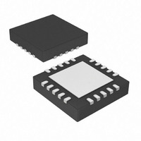
16KB Flash, 512bytes RAM, 256bytes EEPROM, 16MIPS, 1.8-5.5V Operation 20 QFN 4x4
Manufacturer
Microchip Technology
Series
PIC® XLP™ 18Fr
Specifications of PIC18F14K22-E/ML
Core Processor
PIC
Core Size
8-Bit
Speed
48MHz
Connectivity
I²C, LIN, SPI, UART/USART
Peripherals
Brown-out Detect/Reset, POR, PWM, WDT
Number Of I /o
17
Program Memory Size
16KB (8K x 16)
Program Memory Type
FLASH
Eeprom Size
256 x 8
Ram Size
512 x 8
Voltage - Supply (vcc/vdd)
1.8 V ~ 5.5 V
Data Converters
A/D 12x10b
Oscillator Type
Internal
Operating Temperature
-40°C ~ 125°C
Package / Case
20-VQFN Exposed Pad, 20-HVQFN, 20-SQFN, 20-DHVQFN
Lead Free Status / RoHS Status
Lead free / RoHS Compliant
Available stocks
Company
Part Number
Manufacturer
Quantity
Price
Company:

Part Number:
PIC18F14K22-E/ML
Manufacturer:
MICROCHIP
Quantity:
1 000


PIC18F1XK22/LF1XK22
7.7
The IPR registers contain the individual priority bits for the
peripheral interrupts. Due to the number of peripheral
interrupt sources, there are two Peripheral Interrupt
Priority registers (IPR1 and IPR2). Using the priority bits
requires that the Interrupt Priority Enable (IPEN) bit be
set.
REGISTER 7-8:
DS41365D-page 74
bit 7
Legend:
R = Readable bit
-n = Value at POR
bit 7
bit 6
bit 5
bit 4
bit 3
bit 2
bit 1
bit 0
U-0
—
IPR Registers
Unimplemented: Read as ‘0’
ADIP: A/D Converter Interrupt Priority bit
1 = High priority
0 = Low priority
RCIP: EUSART Receive Interrupt Priority bit
1 = High priority
0 = Low priority
TXIP: EUSART Transmit Interrupt Priority bit
1 = High priority
0 = Low priority
SSPIP: Master Synchronous Serial Port Interrupt Priority bit
1 = High priority
0 = Low priority
CCP1IP: CCP1 Interrupt Priority bit
1 = High priority
0 = Low priority
TMR2IP: TMR2 to PR2 Match Interrupt Priority bit
1 = High priority
0 = Low priority
TMR1IP: TMR1 Overflow Interrupt Priority bit
1 = High priority
0 = Low priority
R/W-1
ADIP
IPR1: PERIPHERAL INTERRUPT PRIORITY REGISTER 1
W = Writable bit
‘1’ = Bit is set
R/W-1
RCIP
R/W-1
TXIP
Preliminary
U = Unimplemented bit, read as ‘0’
‘0’ = Bit is cleared
SSPIP
R/W-1
CCP1IP
R/W-1
2010 Microchip Technology Inc.
x = Bit is unknown
TMR2IP
R/W-1
TMR1IP
R/W-1
bit 0
Related parts for PIC18F14K22-E/ML
Image
Part Number
Description
Manufacturer
Datasheet
Request
R

Part Number:
Description:
Manufacturer:
Microchip Technology Inc.
Datasheet:
Part Number:
Description:
Manufacturer:
Microchip Technology Inc.
Datasheet:
Part Number:
Description:
Manufacturer:
Microchip Technology Inc.
Datasheet:
Part Number:
Description:
Manufacturer:
Microchip Technology Inc.
Datasheet:
Part Number:
Description:
Manufacturer:
Microchip Technology Inc.
Datasheet:
Part Number:
Description:
Manufacturer:
Microchip Technology Inc.
Datasheet:
Part Number:
Description:
Manufacturer:
Microchip Technology Inc.
Datasheet:
Part Number:
Description:
Manufacturer:
Microchip Technology Inc.
Datasheet: