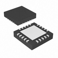
PIC18F14K22-E/ML Microchip Technology, PIC18F14K22-E/ML Datasheet - Page 250

PIC18F14K22-E/ML
Manufacturer Part Number
PIC18F14K22-E/ML
Description
16KB Flash, 512bytes RAM, 256bytes EEPROM, 16MIPS, 1.8-5.5V Operation 20 QFN 4x4
Manufacturer
Microchip Technology
Series
PIC® XLP™ 18Fr
Specifications of PIC18F14K22-E/ML
Core Processor
PIC
Core Size
8-Bit
Speed
48MHz
Connectivity
I²C, LIN, SPI, UART/USART
Peripherals
Brown-out Detect/Reset, POR, PWM, WDT
Number Of I /o
17
Program Memory Size
16KB (8K x 16)
Program Memory Type
FLASH
Eeprom Size
256 x 8
Ram Size
512 x 8
Voltage - Supply (vcc/vdd)
1.8 V ~ 5.5 V
Data Converters
A/D 12x10b
Oscillator Type
Internal
Operating Temperature
-40°C ~ 125°C
Package / Case
20-VQFN Exposed Pad, 20-HVQFN, 20-SQFN, 20-DHVQFN
Lead Free Status / RoHS Status
Lead free / RoHS Compliant
Available stocks
Company
Part Number
Manufacturer
Quantity
Price
Company:
Part Number:
PIC18F14K22-E/ML
Manufacturer:
MICROCHIP
Quantity:
1 000
- Current page: 250 of 388
- Download datasheet (4Mb)
PIC18F1XK22/LF1XK22
REGISTER 21-1:
DS41365D-page 250
bit 7
Legend:
R = Readable bit
-n = Value at POR
bit 7
bit 6
bit 5
bit 4
bit 3
bit 2
bit 1
bit 0
Note 1:
R/W-0
IPEN
2:
3:
If SBOREN is enabled, its Reset state is ‘1’; otherwise, it is ‘0’.
The actual Reset value of POR is determined by the type of device Reset. See the notes following this
register and Section 21.6 “Reset State of Registers” for additional information.
See Table 21-3.
IPEN: Interrupt Priority Enable bit
1 = Enable priority levels on interrupts
0 = Disable priority levels on interrupts (PIC16CXXX Compatibility mode)
SBOREN: BOR Software Enable bit
If BOREN<1:0> = 01:
1 = BOR is enabled
0 = BOR is disabled
If BOREN<1:0> = 00, 10 or 11:
Bit is disabled and read as ‘0’.
Unimplemented: Read as ‘0’
RI: RESET Instruction Flag bit
1 = The RESET instruction was not executed (set by firmware or Power-on Reset)
0 = The RESET instruction was executed causing a device Reset (must be set in firmware after a
TO: Watchdog Time-out Flag bit
1 = Set by power-up, CLRWDT instruction or SLEEP instruction
0 = A WDT time-out occurred
PD: Power-down Detection Flag bit
1 = Set by power-up or by the CLRWDT instruction
0 = Set by execution of the SLEEP instruction
POR: Power-on Reset Status bit
1 = No Power-on Reset occurred
0 = A Power-on Reset occurred (must be set in software after a Power-on Reset occurs)
BOR: Brown-out Reset Status bit
1 = A Brown-out Reset has not occurred (set by firmware only)
0 = A Brown-out Reset occurred (must be set by firmware after a POR or Brown-out Reset occurs)
SBOREN
R/W-1
code-executed Reset occurs)
RCON: RESET CONTROL REGISTER
(1)
W = Writable bit
‘1’ = Bit is set
U-0
—
R/W-1
(2)
(3)
Preliminary
RI
(1)
U = Unimplemented bit, read as ‘0’
‘0’ = Bit is cleared
R-1
TO
R-1
PD
2010 Microchip Technology Inc.
x = Bit is unknown
POR
R/W-0
(2)
R/W-0
BOR
bit 0
Related parts for PIC18F14K22-E/ML
Image
Part Number
Description
Manufacturer
Datasheet
Request
R

Part Number:
Description:
Manufacturer:
Microchip Technology Inc.
Datasheet:

Part Number:
Description:
Manufacturer:
Microchip Technology Inc.
Datasheet:

Part Number:
Description:
Manufacturer:
Microchip Technology Inc.
Datasheet:

Part Number:
Description:
Manufacturer:
Microchip Technology Inc.
Datasheet:

Part Number:
Description:
Manufacturer:
Microchip Technology Inc.
Datasheet:

Part Number:
Description:
Manufacturer:
Microchip Technology Inc.
Datasheet:

Part Number:
Description:
Manufacturer:
Microchip Technology Inc.
Datasheet:

Part Number:
Description:
Manufacturer:
Microchip Technology Inc.
Datasheet:


