PIC18F14K22-E/ML Microchip Technology, PIC18F14K22-E/ML Datasheet - Page 266
PIC18F14K22-E/ML
Manufacturer Part Number
PIC18F14K22-E/ML
Description
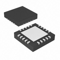
16KB Flash, 512bytes RAM, 256bytes EEPROM, 16MIPS, 1.8-5.5V Operation 20 QFN 4x4
Manufacturer
Microchip Technology
Series
PIC® XLP™ 18Fr
Specifications of PIC18F14K22-E/ML
Core Processor
PIC
Core Size
8-Bit
Speed
48MHz
Connectivity
I²C, LIN, SPI, UART/USART
Peripherals
Brown-out Detect/Reset, POR, PWM, WDT
Number Of I /o
17
Program Memory Size
16KB (8K x 16)
Program Memory Type
FLASH
Eeprom Size
256 x 8
Ram Size
512 x 8
Voltage - Supply (vcc/vdd)
1.8 V ~ 5.5 V
Data Converters
A/D 12x10b
Oscillator Type
Internal
Operating Temperature
-40°C ~ 125°C
Package / Case
20-VQFN Exposed Pad, 20-HVQFN, 20-SQFN, 20-DHVQFN
Lead Free Status / RoHS Status
Lead free / RoHS Compliant
Available stocks
Company
Part Number
Manufacturer
Quantity
Price
Company:

Part Number:
PIC18F14K22-E/ML
Manufacturer:
MICROCHIP
Quantity:
1 000


PIC18F1XK22/LF1XK22
REGISTER 22-4:
REGISTER 22-5:
DS41365D-page 266
bit 7
Legend:
R = Readable bit
-n = Value when device is unprogrammed
bit 7
bit 6-4
bit 3
bit 2-0
bit 7
Legend:
R = Readable bit
-n = Value when device is unprogrammed
bit 7
bit 6
bit 5-4
bit 3
bit 2
bit 1
bit 0
Note 1:
R/W-1
MCLRE
BKBUG
R/P-1
(1)
BKBUG is only used for ICD device. Otherwise, this bit is unimplemented and reads as ‘1’.
MCLRE: MCLR Pin Enable bit
1 = MCLR pin enabled; RA3 input pin disabled
0 = RA3 input pin enabled; MCLR disabled
Unimplemented: Read as ‘0’
HFOFST: HFINTOSC Fast Start-up bit
1 = HFINTOSC starts clocking the CPU without waiting for the oscillator to stabilize.
0 = The system clock is held off until the HFINTOSC is stable.
Unimplemented: Read as ‘0’
BKBUG: Background Debugger Enable bit
1 = Background Debugger disabled
0 = Background Debugger functions enabled
ENHCPU: Enhanced CPU Enable bit
1 = Enhanced CPU enabled
0 = Enhanced CPU disabled
Unimplemented: Read as ‘0’
BBSIZ: Boot BLock Size Select bit
1 = 2 kW boot block size for PIC18F14K22/LF14K22 (1 kW boot block size for
0 = 1 kW boot block size for PIC18F14K22/LF14K22 (512 W boot block size for
LVP: Single-Supply ICSP™ Enable bit
1 = Single-Supply ICSP enabled
0 = Single-Supply ICSP disabled
Unimplemented: Read as ‘0’
STVREN: Stack Full/Underflow Reset Enable bit
1 = Stack full/underflow will cause Reset
0 = Stack full/underflow will not cause Reset
ENHCPU
R/W-0
PIC18F13K22/LF13K22)
PIC18F13K22/LF13K22)
U-0
—
CONFIG3H: CONFIGURATION REGISTER 3 HIGH
CONFIG4L: CONFIGURATION REGISTER 4 LOW
P = Programmable bit
P = Programmable bit
U-0
U-0
—
—
U-0
U-0
Preliminary
—
—
(1)
U = Unimplemented bit, read as ‘0’
x = Bit is unknown
U = Unimplemented bit, read as ‘0’
x = Bit is unknown
HFOFST
BBSIZ
R/P-1
R/P-0
R/P-1
LVP
U-0
—
2010 Microchip Technology Inc.
U-0
U-0
—
—
STVREN
R/P-1
U-0
—
bit 0
bit 0
Related parts for PIC18F14K22-E/ML
Image
Part Number
Description
Manufacturer
Datasheet
Request
R

Part Number:
Description:
Manufacturer:
Microchip Technology Inc.
Datasheet:
Part Number:
Description:
Manufacturer:
Microchip Technology Inc.
Datasheet:
Part Number:
Description:
Manufacturer:
Microchip Technology Inc.
Datasheet:
Part Number:
Description:
Manufacturer:
Microchip Technology Inc.
Datasheet:
Part Number:
Description:
Manufacturer:
Microchip Technology Inc.
Datasheet:
Part Number:
Description:
Manufacturer:
Microchip Technology Inc.
Datasheet:
Part Number:
Description:
Manufacturer:
Microchip Technology Inc.
Datasheet:
Part Number:
Description:
Manufacturer:
Microchip Technology Inc.
Datasheet: