MICRF505YML TR Micrel Inc, MICRF505YML TR Datasheet - Page 32
MICRF505YML TR
Manufacturer Part Number
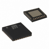
MICRF505YML TR
Description
868-915 MHz ISM Band Transceiver( )
Manufacturer
Micrel Inc
Specifications of MICRF505YML TR
Frequency
850MHz ~ 950MHz
Data Rate - Maximum
200kbps
Modulation Or Protocol
FSK
Applications
Telemetry, Wireless Controller
Power - Output
10dBm
Sensitivity
-111dBm
Voltage - Supply
2.3 V ~ 5.5 V
Current - Receiving
13.5mA
Current - Transmitting
28mA
Data Interface
PCB, Surface Mount
Antenna Connector
PCB, Surface Mount
Operating Temperature
-40°C ~ 85°C
Package / Case
32-MLF®, QFN
Operating Temperature (min)
-40C
Operating Temperature (max)
85C
Operating Temperature Classification
Industrial
Modulation Type
FSK
Lead Free Status / RoHS Status
Lead free / RoHS Compliant
Memory Size
-
Lead Free Status / Rohs Status
Compliant
Other names
576-1659-2
MICRF505YMLTR
MICRF505YMLTR


Layout Considerations
The MICRF505 is a highly integrated RF IC with only a few “hot” pins, however it is suggested to study available
reference design on
October 2006
•
•
•
•
•
•
•
•
To ensure the best RF design it is important to plan the layout and dedicate area for the different circuitry.
Good RF engineering is to start with the RF circuitry making sure that general RF guidelines are met
(following points). Separate noisy circuitry and RF by placing it on the opposite side maximizing the
distance between the circuitry. The RF circuitry should be placed as close to what is considered the
ground spot (EG battery) to avoid ground currents. Place the RF circuitry in a position that ensure as
short and straight trace to the antenna connection to avoid reflections.
Proper ground is needed. If the PCB is 2-layer, the bottom layer should be kept only for ground. Avoid
signal traces that split the ground plane. For a 4-layer PCB, it is recommended to keep the second layer
only for ground.
A ground via should be placed close to all the ground pins. The bottom ground (heat sink) pad should be
penetrated with >9 ground via’s. These via’s should be “open” or “plugged” to avoid air pockets caused by
the solder paste. If such air pockets appear, the air will expand during the reflow process and may/will
cause the device to twist/move.
The antenna pin (pin 5) has an impedance of ~50 ohm. The antenna trace should be kept to 50 ohm to
avoid signal reflection and loss of performance. Minor deviations can be compensated by matching the
LC filter. Any transmission line calculator can be used to find the needed trace width given a board build
up. Ex: A trace width of 75 mil (1.9 mm) gives 50 impedance on a FR4 board (dielectric cons=4.4) with
copper thickness of 35 µ m and height (layer 1-layer 2 spacing) of 1.00 mm.
RF circuitry is sensitive to voltage supply and therefore caution should be taken when choosing power
circuitry. To achieve the best performance, low noise LDO’s with high PSSR should be chosen. What is
present on the voltage supply will be directly modulated to the RF spectrum causing degradation and
regulatory issues. To make sure you have the right selection, please contact local sales for the latest
Micrel offerings in power management and guidance. To avoid “pickup” from other circuitry on the VDD
lines, it is recommended to route the VDD in a star configuration with decoupling at each circuitry and at
the common connection point (see above layout). If there is noisy circuitry in the design, it is strongly
recommended to use a separate power supply and/or place low value resistors (10ohms), inductors in
series with the power supply line into these circuitry.
It is recommended to connect the PLL loop filter to VDD (C1, C3 and R1). The VDD connection should be
placed as close to pin 31 (VCOVDD) as possible. The MICRF505 has a integrated VCO where the
resonator circuit (varactor ) has a reference to VDD. With a common reference point, the MICRF505
(PLL) will somewhat compensate for noise present on the VDD.
PLL loop filter components C1, C2, C3, R1 and R2 should have a compact layout and should be placed
as close to pin 27 and 29. Avoid signal traces/bus and noisy circuitry around/close/under this area.
Digital high speed logic or noisy circuitry should/must be at a safe distance from RF circuitry or RF VDD
as this might/will cause degradation of sensitivity and create spurious emissions. Example of such
circuitry is LCD display, charge pumps, RS232, clock / data bus etc.
www.micrel.com
before starting with schematics and layout.
32
+1 408-944-0800
M9999-103106
Related parts for MICRF505YML TR
Image
Part Number
Description
Manufacturer
Datasheet
Request
R

Part Number:
Description:
Manufacturer:
Micrel Inc
Datasheet:
Part Number:
Description:
Manufacturer:
Micrel Inc
Datasheet:
Part Number:
Description:
Manufacturer:
Micrel Inc
Datasheet:
Part Number:
Description:
Manufacturer:
Micrel Inc
Datasheet:
Part Number:
Description:
Manufacturer:
Micrel Inc
Datasheet:
Part Number:
Description:
Manufacturer:
Micrel Inc
Datasheet:
Part Number:
Description:
Manufacturer:
Micrel Inc
Datasheet:
Part Number:
Description:
Manufacturer:
Micrel Inc
Datasheet:
Part Number:
Description:
Manufacturer:
Micrel Inc
Datasheet:
Part Number:
Description:
Manufacturer:
Micrel Inc
Datasheet:
Part Number:
Description:
Manufacturer:
Micrel Inc
Datasheet:
Part Number:
Description:
Manufacturer:
Micrel Inc
Datasheet:
Part Number:
Description:
Manufacturer:
Micrel Inc
Datasheet:
Part Number:
Description:
Manufacturer:
Micrel Inc
Datasheet: