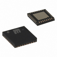
MICRF505YML TR Micrel Inc, MICRF505YML TR Datasheet - Page 20

MICRF505YML TR
Manufacturer Part Number
MICRF505YML TR
Description
868-915 MHz ISM Band Transceiver( )
Manufacturer
Micrel Inc
Specifications of MICRF505YML TR
Frequency
850MHz ~ 950MHz
Data Rate - Maximum
200kbps
Modulation Or Protocol
FSK
Applications
Telemetry, Wireless Controller
Power - Output
10dBm
Sensitivity
-111dBm
Voltage - Supply
2.3 V ~ 5.5 V
Current - Receiving
13.5mA
Current - Transmitting
28mA
Data Interface
PCB, Surface Mount
Antenna Connector
PCB, Surface Mount
Operating Temperature
-40°C ~ 85°C
Package / Case
32-MLF®, QFN
Operating Temperature (min)
-40C
Operating Temperature (max)
85C
Operating Temperature Classification
Industrial
Modulation Type
FSK
Lead Free Status / RoHS Status
Lead free / RoHS Compliant
Memory Size
-
Lead Free Status / Rohs Status
Compliant
Other names
576-1659-2
MICRF505YMLTR
MICRF505YMLTR
Receiver
The receiver is a zero intermediate frequency (IF)
type in order to make channel filtering possible with
low-power integrated low-pass filters. The receiver
consists of a low noise amplifier (LNA) that drives a
quadrature mixer pair. The mixer outputs feed two
identical signal channels in phase quadrature. Each
channel include a pre-amplifier, a third order Sallen-
Key RC lowpass filter from strong adjacent channel
signals and finally a limiter. The main channel filter is
a switched-capacitor implementation of a six-pole
elliptic lowpass filte. The elliptic filter minimizes the
total capacitance required for a given selectivity and
dynamic range. The cut-off frequency of the Sallen-
Key RC filter can be programmed to four different
frequencies: 100kHz, 150kHz, 230kHz and 340kHz.
The demodulator demodulates the I and Q channel
outputs and produces a digital data output. If detects
the relative phase of the I and Q channel signal. If
the I channel signal lags the Q channel, the FSK
tone frequency lies above the LO frequency (data
‘1’). If the I channel leads the Q channel, the FSK
tone lies below the LO frequency (data ‘0’). The
output of the receiver is available on the DataIXO
pin. A RSSI circuit (receive signal strength indicator)
indicates the received signal level.
Front End
A low noise amplifier in RF receivers is used to
boost the incoming signal prior to the frequency
conversion process. This is important in order to
prevent mixer noise from dominating the overall
front-end noise performance. The LNA is a two-
stage amplifier and has a nominal gain of
approximately 23dB at 900MHz. The front end has a
gain of about 33dB to 35dB. The gain varies by 1-
1.5dB over a 2.0V to 2.5V variation in power supply.
The LNA can be bypassed by setting bit LNA_by to
‘1’. This can be useful for very strong input signal
levels. The front-end gain with the LNA bypassed is
about 9-10dB. The mixers have a going of about
10dB at 915MHz. The differential outputs of the
mixers can be made available at pins IchOut and
QchOut. The output impedance of each mixer is
about 8k Ω .
The input impedance is close to 50 Ω as shown in
Figure 12, giving an input reflection of about -20dB.
The receiver does not require any matching network
to optimize the gain. However, a matching network is
recommended for harmonic suppression in Tx and
for improved selectivity in Rx.
0000000
A6..A0
October 2006
LNA_by
D7
PA2
D6
PA1
D5
PA0
D4
Sync_en
D3
Mode1
D2
Mode0
D1
Load_en
D0
20
0000001
A6..A0
Sallen-Key Filters
Each channel includes a pre-amplifier and a prefilter,
which is a three-pole Sallen-Key lowpass filter. It
protects the following switched-capacitor filter from
strong adjacent channel signals, and it also works as
an anti-aliasing filter. The preamplifier has a gain of
22-23dB. The maximum output voltage swing is
about 1.4Vpp for a 2.25V power supply. In addition,
the IF amplifier also performs offset cancellation.
Gain varies by less than 0.5dB over a 2.0 – 2.5V
variation in power supply. The third order Sallen-Key
lowpass filter is programmable to four different cut-
off frequencies according to the table below:
Modulation1
PF_FC1
D7
0
0
1
1
Figure 12. LNA Input Impedance
Modulation0
D6
PF_FC0
0
1
0
1
D5
‘0’
D4
‘0’
RSSI_en
D3
Cut-off Freq. (kHz)
+1 408-944-0800
LD_en
M9999-103106
D2
100
150
230
340
PF_FC1
D1
PF_FC0
D0


