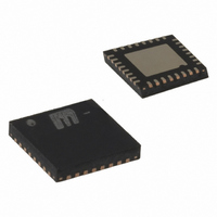
MICRF505YML TR Micrel Inc, MICRF505YML TR Datasheet - Page 25

MICRF505YML TR
Manufacturer Part Number
MICRF505YML TR
Description
868-915 MHz ISM Band Transceiver( )
Manufacturer
Micrel Inc
Specifications of MICRF505YML TR
Frequency
850MHz ~ 950MHz
Data Rate - Maximum
200kbps
Modulation Or Protocol
FSK
Applications
Telemetry, Wireless Controller
Power - Output
10dBm
Sensitivity
-111dBm
Voltage - Supply
2.3 V ~ 5.5 V
Current - Receiving
13.5mA
Current - Transmitting
28mA
Data Interface
PCB, Surface Mount
Antenna Connector
PCB, Surface Mount
Operating Temperature
-40°C ~ 85°C
Package / Case
32-MLF®, QFN
Operating Temperature (min)
-40C
Operating Temperature (max)
85C
Operating Temperature Classification
Industrial
Modulation Type
FSK
Lead Free Status / RoHS Status
Lead free / RoHS Compliant
Memory Size
-
Lead Free Status / Rohs Status
Compliant
Other names
576-1659-2
MICRF505YMLTR
MICRF505YMLTR
Another much more efficient encoding type is 3B4B
where three data bits are encoded into a four-bit
word. The reason for encoding is to minimize the DC
component in the modulated data. To have minimum
DC component each four bit word should include
two elements of “1” and two elements of “0”.
Following this guidance only 6 out of 8 word
complies and two encoded words needs special
precaution. Whenever 000 and 111 data appear, the
user must set/clear a flag that indicate if last
encoded word was “Word A” and select the
respective encoded word shown in Table 11.
Data bits
000 000 000 000 000
111 111 010 110 000
When Modulation1 Modulation0 is 10, two sets of
October 2006
Data
000
001
010
011
100
101
110
111
Table 14. Example of 3B4B encoding
Table 13. 3B4B Encoding
Encoded words
1011 0100 1011 0100 1011
1101 0010 0011 0110 1011
Word A
1011
1100
0011
1010
0101
1001
0110
1101
Comments
A Flag indicates if “Word
A” has been used
A Flag indicates if “Word
A” has been used
Word B
0100
0010
25
divider values need to be programmed. The formula
for calculating the M, N and A values is given in
chapter Frequency synthesizer. The divider values
stored in the M0-, N0-, and A0- registers will be used
when transmitting a ‘0’ and the M1-, N1-, and A1-
registers will be used to transmit a ‘1’. The difference
between the two carrier frequencies corresponds to
the double sided frequency modulation. Opposite
from the modulation with the modulator, the PLL
shall now lock on a new frequency for every change
in the transmitted data. The PLL bandwidth therefore
needs to be relatively high, higher bit rate requires a
higher PLL bandwidth and vice versa. The data to
be transmitted shall be applied to pin DataIXO (see
chapter Transceiver sync-/non-synchronous mode
on how to use the pin DataClk). The DataIXO pin is
set as input in transmit mode and output in receive
mode. When set as input, a weak voltage divider will
set the level to Vdd/2, when it is not pulled up or
down by the controller. When using the modulator, it
is important that the DataIXO is kept tristated until
the transmission shall begin (when PLL is in lock
and the PA is turned on). When Data IXO is
tristated, the PLL will lock on the LO frequency
(used in receive mode). When DataIXO is set either
high or low, the RF frequency will be shifted up or
down, centered around the LO-frequency. This is
only important when using the modulator, for the
other modulation method, if DATAIXO is tristated,
the M0-, N0- and A0-registers will be used.
+1 408-944-0800
M9999-103106


