MRF1518NT1 Freescale Semiconductor, MRF1518NT1 Datasheet - Page 13
MRF1518NT1
Manufacturer Part Number
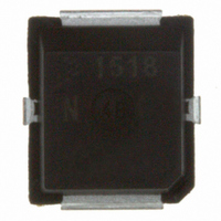
MRF1518NT1
Description
IC MOSFET RF N-CHAN PLD-1.5
Manufacturer
Freescale Semiconductor
Datasheet
1.MRF1518NT1.pdf
(19 pages)
Specifications of MRF1518NT1
Transistor Type
N-Channel
Frequency
520MHz
Gain
13dB
Voltage - Rated
40V
Current Rating
4A
Current - Test
150mA
Voltage - Test
12.5V
Power - Output
8W
Package / Case
PLD-1.5
Configuration
Single Dual Source
Drain-source Breakdown Voltage
40 V
Gate-source Breakdown Voltage
+/- 20 V
Continuous Drain Current
4 A
Power Dissipation
62500 mW
Maximum Operating Temperature
+ 150 C
Minimum Operating Temperature
- 65 C
Mounting Style
SMD/SMT
Transistor Polarity
N-Channel
Drain Source Voltage Vds
40V
Continuous Drain Current Id
4mA
Power Dissipation Pd
62.5W
Rf Transistor Case
PLD-1.5
Termination Type
SMD
Output Power Pout
8W
Rohs Compliant
Yes
Filter Terminals
SMD
Gate-source Voltage
20V
Lead Free Status / RoHS Status
Contains lead / RoHS non-compliant
Noise Figure
-
Lead Free Status / Rohs Status
Lead free / RoHS Compliant
Other names
MRF1518NT1
MRF1518NT1TR
MRF1518NT1TR
Available stocks
Company
Part Number
Manufacturer
Quantity
Price
Company:

Part Number:
MRF1518NT1
Manufacturer:
FREESCALE
Quantity:
1 400


RF Device Data
Freescale Semiconductor
Note: Z
Z
Z
in
OL
Figure 38. Series Equivalent Input and Output Impedance (continued)
* = Complex conjugate of the load
V
MHz
400
440
470
= Complex conjugate of source
OL
DD
f
* was chosen based on tradeoffs between gain, drain efficiency, and device stability.
400
impedance with parallel 15 Ω
resistor and 47 pF capacitor in
series with gate. (See Figure 19).
impedance at given output power,
voltage, frequency, and η
= 12.5 V, I
Z
f = 470 MHz
OL
*
4.28 +j2.36
400
6.45 +j5.13
5.91 +j3.34
DQ
Input
Matching
Network
Z
Ω
= 150 mA, P
in
f = 175 MHz
f = 470 MHz
135
Z
in
4.41 +j0.67
4.14 +j2.53
3.92 +j4.02
out
Z
Z
Z
in
OL
= 8 W
OL
Ω
D
*
*
> 50 %.
Device
Under Test
f = 135 MHz
Z
in
175
Z
Z
in
OL
Z
* = Complex conjugate of the load
OL
MHz
135
155
175
V
= Complex conjugate of source
*
DD
f
Z
impedance with parallel 15 Ω
resistor and 43 pF capacitor in
series with gate. (See Figure 28).
impedance at given output power,
voltage, frequency, and η
= 12.5 V, I
o
= 10 Ω
Output
Matching
Network
18.31 - j0.76
17.72 +j1.85
18.06 +j5.23
DQ
Z
Ω
= 150 mA, P
in
8.97 +j2.62
9.69 +j2.81
7.94 +j1.14
out
Z
= 8 W
D
OL
Ω
> 50 %.
*
MRF1518NT1
13
Related parts for MRF1518NT1
Image
Part Number
Description
Manufacturer
Datasheet
Request
R

Part Number:
Description:
MRF1518RF Power Field Effect Transistor
Manufacturer:
Freescale Semiconductor, Inc


Part Number:
Description:
Fast Acting Radial Lead Micro Fuse Series
Manufacturer:
BEL [Bel Fuse Inc.]
Datasheet:

Part Number:
Description:
FUSE 1A 250V FAST SHORT MRF
Manufacturer:
Bel Fuse Inc
Datasheet:
Part Number:
Description:
Manufacturer:
Freescale Semiconductor, Inc
Datasheet:
Part Number:
Description:
Manufacturer:
Freescale Semiconductor, Inc
Datasheet:
Part Number:
Description:
Manufacturer:
Freescale Semiconductor, Inc
Datasheet:
Part Number:
Description:
Manufacturer:
Freescale Semiconductor, Inc
Datasheet:
Part Number:
Description:
Manufacturer:
Freescale Semiconductor, Inc
Datasheet:
Part Number:
Description:
Manufacturer:
Freescale Semiconductor, Inc
Datasheet:
Part Number:
Description:
Manufacturer:
Freescale Semiconductor, Inc
Datasheet:
Part Number:
Description:
Manufacturer:
Freescale Semiconductor, Inc
Datasheet:
Part Number:
Description:
Manufacturer:
Freescale Semiconductor, Inc
Datasheet:
Part Number:
Description:
Manufacturer:
Freescale Semiconductor, Inc
Datasheet:
Part Number:
Description:
Manufacturer:
Freescale Semiconductor, Inc
Datasheet: