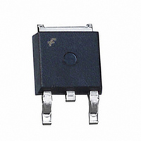
FQD8P10TM Fairchild Semiconductor, FQD8P10TM Datasheet - Page 2

FQD8P10TM
Manufacturer Part Number
FQD8P10TM
Description
MOSFET P-CH 100V 6.6A DPAK
Manufacturer
Fairchild Semiconductor
Series
QFET™r
Specifications of FQD8P10TM
Fet Type
MOSFET P-Channel, Metal Oxide
Fet Feature
Standard
Rds On (max) @ Id, Vgs
530 mOhm @ 3.3A, 10V
Drain To Source Voltage (vdss)
100V
Current - Continuous Drain (id) @ 25° C
6.6A
Vgs(th) (max) @ Id
4V @ 250µA
Gate Charge (qg) @ Vgs
15nC @ 10V
Input Capacitance (ciss) @ Vds
470pF @ 25V
Power - Max
2.5W
Mounting Type
Surface Mount
Package / Case
DPak, TO-252 (2 leads+tab), SC-63
Configuration
Single
Transistor Polarity
P-Channel
Resistance Drain-source Rds (on)
0.53 Ohms
Forward Transconductance Gfs (max / Min)
4.1 S
Drain-source Breakdown Voltage
- 100 V
Gate-source Breakdown Voltage
+/- 30 V
Continuous Drain Current
- 6.6 A
Power Dissipation
2.5 W
Maximum Operating Temperature
+ 150 C
Mounting Style
SMD/SMT
Minimum Operating Temperature
- 55 C
Lead Free Status / RoHS Status
Lead free / RoHS Compliant
Available stocks
Company
Part Number
Manufacturer
Quantity
Price
Company:
Part Number:
FQD8P10TM_F085
Manufacturer:
FAIRCHILD
Quantity:
5 000
D-PAK Tape and Reel Data, continued
D-PAK TM / XM
D-PAK TM / XM
D-PAK TF / X
D-PAK TF / X
D-PAK Reel
Configuration: Figure 4.0
Pkg type
Pkg type
(16mm)
(16mm)
(16mm)
(16mm)
Notes: A0, B0, and K0 dimensions are determined with respect to the EIA/Jedec RS-481
D-PAK Embossed Carrier Tape
Configuration: Figure 3.0
10 deg maximum component rotation
Tape Size
Tape Size
16mm
16mm
Dim A
Dim A
Sketch A (Side or Front Sectional View)
Component Rotation
max
max
T
Tc
rotational and lateral movement requirements (see sketches A, B, and C).
K0
Wc
+/-0.10
+/-0.10
+/-0.10
+/-0.10
10.80
10.80
7.10
7.10
A0
A0
13?Dia
13?Dia
Option
Option
Reel
Reel
+/-0.10
+/-0.10
+/-0.10
+/-0.10
13” Diameter Option
10.50
10.50
7.20
7.20
B0
B0
B0
13.00
13.00
330
330
Dim A
Dim A
+/-0.3
+/-0.3
+/-0.3
+/-0.3
16.0
16.0
16.0
16.0
W
W
0.059
0.059
1.5
1.5
Dim B
Dim B
+0.10
+0.10
/-0.00
/-0.00
/-0.00
/-0.00
+0.10
+0.10
1.50
1.50
1.50
1.50
D0
D0
B0
B0
B0
A0
Sketch B (Top View)
Sketch B (Top View)
Component Rotation
Component Rotation
0.512 +0.020/-0.008
0.512 +0.020/-0.008
13 +0.5/-0.2
13 +0.5/-0.2
Dimensions are in inches and millimeters
Dimensions are in inches and millimeters
User Direction of Feed
User Direction of Feed
+/-0.10
+/-0.10
+/-0.10
+/-0.10
D1
D1
1.7
1.7
1.7
1.7
A0
A0
A0
Dim C
Dim C
Dimensions are in millimeter
Dimensions are in millimeter
10 deg maximum
10 deg maximum
10 deg maximum
See detail AA
See detail AA
P0
W2 max Measured at Hub
+/-0.10
+/-0.10
+/-0.10
+/-0.10
Typical
Typical
Typical
component
component
component
center line
center line
center line
1.75
1.75
1.75
1.75
Typical
Typical
Typical
component
component
component
cavity
cavity
cavity
center line
center line
center line
E1
E1
Dim N
P1
W1 Measured at Hub
0.795
0.795
20.2
20.2
Dim D
Dim D
14.25
14.25
14.25
14.25
min
min
E2
E2
min
min
D0
D1
4.00
4.00
100
100
+/-0.10
+/-0.10
+/-0.10
+/-0.10
Dim N
Dim N
W3
7.50
7.50
7.50
7.50
0.8mm
maximum
F
F
Sketch C (Top View)
Component lateral movement
TM Type
Dim D
Dim D
min
min
0.646 +0.078/-0.000
0.646 +0.078/-0.000
16.4 +2/0
16.4 +2/0
+/-0.1
+/-0.1
+/-0.1
+/-0.1
12.0
12.0
P1
P1
8.0
8.0
Dim W1
Dim W1
1.4mm
maximum
+/-0.1
+/-0.1
+/-0.1
+/-0.1
P0
P0
4.0
4.0
4.0
4.0
DETAIL AA
DETAIL AA
+/-0.10
+/-0.10
+/-0.10
+/-0.10
2.65
2.65
2.70
2.70
K0
K0
0.882
0.882
22.4
22.4
Dim W2
Dim W2
1.7mm
maximum
F
Sketch C (Top View)
Component lateral movement
E1
E2
+/-0.05
+/-0.05
+/-0.05
+/-0.05
TF Type
B Min
B Min
0.30
0.30
0.30
0.30
September 2003, Rev. C1
T
T
W
0.626 ? 0.764
0.626 ? 0.764
15.9 ? 19.4
15.9 ? 19.4
Dim W3 (LSL-USL)
Dim W3 (LSL-USL)
Dim C
Dim C
+/-0.1
+/-0.1
+/-0.1
+/-0.1
Wc
Wc
13.3
13.3
13.3
13.3
0.9mm
maximum
0.10
0.10
0.10
0.10
max
max
Tc
Tc
max
max


