85134F AGILENT TECHNOLOGIES, 85134F Datasheet - Page 23
85134F
Manufacturer Part Number
85134F
Description
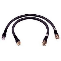
Cable Sets
Manufacturer
AGILENT TECHNOLOGIES
Datasheet
1.85134F.pdf
(47 pages)
Specifications of 85134F
Kit Contents
2 Cables
Peak Reflow Compatible (260 C)
No
Cable Length
24.75"
Leaded Process Compatible
No
Connector Type B
3.5mm Female
Connector Type A
2.4mm Female
Lead Length
62.9cm
Lead Free Status / RoHS Status
Contains lead / RoHS non-compliant


Gaging Procedures
Gaging 2.4 mm, 3.5 mm, and 7 mm Connectors
NOTE
1. Select the proper gage for your connector. Refer to
2. Inspect and clean the gage, gage master, and device to be gaged. Refer to
3. Zero the connector gage (refer to
4. Gage the device connector (refer to
85134E/F/H & 85135E/F
numbers.
Inspection”
a. While holding the gage by the barrel, and without turning the gage or the device,
b. Using an open-end wrench to keep the device body from rotating, use the torque
c. As you watch the gage pointer, gently tap the barrel of the gage to settle the reading.
d. Remove the gage master.
a. While holding the gage by the barrel, and without turning the gage or the device,
b. Using an open-end wrench to keep the device body from rotating, use the torque
c. Gently tap the barrel of the gage with your finger to settle the gage reading.
d. Read the gage indicator dial.
connect the gage to the gage master by interconnecting the male and female
connectors. Connect the nut finger tight. Do not overtighten.
wrench included in the kit to tighten the connecting nut to the specified torque.
Refer to
information.
The gage pointer should line up exactly with the zero mark on the gage.
2.4 mm and 3.5 mm gages: If not, adjust the zero set knob until the gage pointer
lines up exactly with the zero mark.
7 mm gage: If not, loosen the dial lock screw on the gage and rotate the gage dial so
that the pointer is aligned with the zero mark. Tighten the dial screw lock.
connect the gage to the device. Connect the nut finger-tight. Do not overtighten.
wrench recommended for use to tighten the connecting nut to the specified torque.
Refer to
information.
2.4 mm and 3.5 mm gages: Read only the black ± signs; not the red ± signs.
7 mm gage: If the needle has moved clockwise, the center conductor is protruding by
and amount indicated by the black numbers. If the needle has moved
counterclockwise, the center conductor is recessed by an amount indicated by the red
numbers.
Always hold a connector gage by the gage barrel, below the dial indicator.
This gives the best stability, and improves measurement accuracy. (Cradling
the gage in your hand or holding it by the dial applies stress to the gage
plunger mechanism through the dial indicator housing.)
“Final Connection Using a Torque Wrench” on page 3-14
“Final Connection Using a Torque Wrench” on page 3-14
and
“Cleaning Connectors”
Figure
Figure 3-3
earlier in this chapter.
3-3):
and
Table 4-1 on page 4-4
Figure
Use, Maintenance, and Care of the Cables
3-4):
for additional
for additional
for gage part
Gaging Connectors
“Visual
3-9