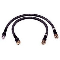
85134F AGILENT TECHNOLOGIES, 85134F Datasheet - Page 22

85134F
Manufacturer Part Number
85134F
Description
Cable Sets
Manufacturer
AGILENT TECHNOLOGIES
Datasheet
1.85134F.pdf
(47 pages)
Specifications of 85134F
Kit Contents
2 Cables
Peak Reflow Compatible (260 C)
No
Cable Length
24.75"
Leaded Process Compatible
No
Connector Type B
3.5mm Female
Connector Type A
2.4mm Female
Lead Length
62.9cm
Lead Free Status / RoHS Status
Contains lead / RoHS non-compliant
Use, Maintenance, and Care of the Cables
Gaging Connectors
Reading the 7mm Connector Gage
When making a measurement, the gage dial indicator will travel in one of two directions. If
the center conductor is recessed from the zero reference plane, the indicator will move
counterclockwise to indicate the amount of recession, which is read as a negative value. If
the center conductor protrudes, the indicator will move clockwise to indicate the amount of
protrusion, which is read as a positive value. Refer to
page 2-3
Figure 3-2
3-8
The gage dial is divided into increments of 0.0001 inch and major divisions of 0.001 inch
(see
of 0.01 inch. Use the small dial as the indicator of multiples of 0.01 inch. In most
connector measuring applications, this value will be zero.
Figure
for definitions of protrusion and recession.
3-2). For each revolution of the large dial, the smaller dial indicates a change
Reading the Connector Gage
“Center Conductor Pin Depth” on
85134E/F/H & 85135E/F


