85134F AGILENT TECHNOLOGIES, 85134F Datasheet - Page 17
85134F
Manufacturer Part Number
85134F
Description
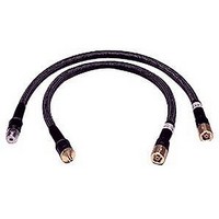
Cable Sets
Manufacturer
AGILENT TECHNOLOGIES
Datasheet
1.85134F.pdf
(47 pages)
Specifications of 85134F
Kit Contents
2 Cables
Peak Reflow Compatible (260 C)
No
Cable Length
24.75"
Leaded Process Compatible
No
Connector Type B
3.5mm Female
Connector Type A
2.4mm Female
Lead Length
62.9cm
Lead Free Status / RoHS Status
Contains lead / RoHS non-compliant


Use, Maintenance, and Care of the Cables
Visual Inspection
Visual Inspection
Visual inspection and, if necessary, cleaning should be done every time a connection is
made. Metal particles from the connector threads may fall onto the mating plane surface of
the connector when it is disconnected. One connection made with a dirty or damaged
connector can damage both connectors beyond repair.
Magnification is helpful when inspecting connectors, but it is not required and may
actually be misleading. Defects and damage that cannot be seen without magnification
generally have no effect on electrical or mechanical performance. Magnification is of great
use in analyzing the nature and cause of the damage and in cleaning connectors, but it is
not required for inspection. Use the following guidelines when evaluating the integrity of a
connector.
Look for Obvious Defects and Damage First
Examine the connector first for obvious defects and damage: badly worn plating on the
connector interface, deformed threads, or bent, broken, or misaligned center conductors.
Connector nuts should move smoothly and be free of burrs, loose metal particles, and
rough spots.
What Causes Connector Wear?
Connector wear is caused by connecting and disconnecting the cable. The more use a
connector gets, the faster it wears and degrades. The wear is greatly accelerated when
connectors are not kept clean, or are connected incorrectly.
Connector wear eventually degrades performance of the cable. Replace cables with worn
connectors.
The test port connectors on the network analyzer test set may have many connections each
day, and are therefore also subject to wear. It is recommended that an adapter be used as a
test port saver to minimize the wear on the test set’s test port connectors.
Inspect the Mating Plane Surfaces
Flat contact between the connectors at all points on their mating plane surfaces is required
for a good connection. Look especially for deep scratches or dents, and for dirt and metal
particles on the connector mating plane surfaces. Also look for signs of damage due to
excessive or uneven wear or misalignment.
Light burnishing of the mating plane surfaces is normal, and is evident as light scratches
or shallow circular marks distributed more or less uniformly over the mating plane
surface. Other small defects and cosmetic imperfections are also normal. None of these
affect electrical or mechanical performance.
If a connector shows deep scratches or dents, particles clinging to the mating plane
surfaces, or uneven wear, clean and inspect it again. Cables with damaged connectors
should be repaired or discarded. Determine the cause of damage before connecting a new,
undamaged connector in the same configuration.
85134E/F/H & 85135E/F
3-3