HGTP5N120BND Fairchild Semiconductor, HGTP5N120BND Datasheet
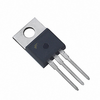
IGBT NPT N-CH 1200V 21A TO-220AB

HGTP5N120BND

Manufacturer Part Number
HGTP5N120BND
Description
IGBT NPT N-CH 1200V 21A TO-220AB
Manufacturer
Fairchild Semiconductor
Datasheet

Specifications of HGTP5N120BND

Igbt Type
NPT
Voltage - Collector Emitter Breakdown (max)
1200V
Vce(on) (max) @ Vge, Ic
2.7V @ 15V, 5A
Current - Collector (ic) (max)
21A
Power - Max
167W
Input Type
Standard
Mounting Type
Through Hole
Package / Case
TO-220-3 (Straight Leads)
Channel Type
N
Configuration
Single
Collector-emitter Voltage
1.2kV
Gate To Emitter Voltage (max)
±20V
Package Type
TO-220AB
Pin Count
3 +Tab
Mounting
Through Hole
Operating Temperature (min)
-55
Operating Temperature (max)
150C
Operating Temperature Classification
Military
Collector- Emitter Voltage Vceo Max
1200 V
Collector-emitter Saturation Voltage
2.45 V
Maximum Gate Emitter Voltage
+/- 20 V
Continuous Collector Current At 25 C
21 A
Gate-emitter Leakage Current
+/- 250 nA
Power Dissipation
167 W
Maximum Operating Temperature
+ 150 C
Continuous Collector Current Ic Max
21 A
Minimum Operating Temperature
- 55 C
Mounting Style
Through Hole
Lead Free Status / RoHS Status
Lead free / RoHS Compliant

Available stocks

Company
Part Number
Manufacturer
Quantity
Price
Part Number:
HGTP5N120BND
Manufacturer:
FSC
Quantity:
10 000
Part Number:
HGTP5N120BND
Manufacturer:
FAIRCHILD/仙童
Quantity:
20 000
Part Number:
HGTP5N120BND
0
Company:
Part Number:
HGTP5N120BND
Quantity:
77 600
©2003 Fairchild Semiconductor Corporation
21A, 1200V, NPT Series N-Channel IGBTs
with Anti-Parallel Hyperfast Diodes
The HGTG5N120BND and HGTP5N120BND are Non-
Punch Through (NPT) IGBT designs. They are new
members of the MOS gated high voltage switching IGBT
family. IGBTs combine the best features of MOSFETs and
bipolar transistors. This device has the high input impedance
of a MOSFET and the low on-state conduction loss of a
bipolar transistor. The IGBT used is the development type
TA49308. The Diode used is the development type TA49058
(Part number RHRD6120).
The IGBT is ideal for many high voltage switching
applications operating at moderate frequencies where low
conduction losses are essential, such as: AC and DC motor
controls, power supplies and drivers for solenoids, relays
and contactors.
Formerly Developmental Type TA49306.
Ordering Information
NOTE: When ordering, use the entire part number. i.e.,
HGTG5N120BND.
Symbol
HGTG5N120BND
HGTP5N120BND
4,364,073
4,598,461
4,682,195
4,803,533
4,888,627
PART NUMBER
FAIRCHILD SEMICONDUCTOR IGBT PRODUCT IS COVERED BY ONE OR MORE OF THE FOLLOWING U.S. PATENTS
4,417,385
4,605,948
4,684,413
4,809,045
4,890,143
G
TO-247
TO-220AB
PACKAGE
C
E
Data Sheet
4,430,792
4,620,211
4,694,313
4,809,047
4,901,127
5N120BND
5N120BND
BRAND
4,443,931
4,631,564
4,717,679
4,810,665
4,904,609
HGTG5N120BND, HGTP5N120BND
4,466,176
4,639,754
4,743,952
4,823,176
4,933,740
Features
• 21A, 1200V, T
• 1200V Switching SOA Capability
• Typical Fall Time . . . . . . . . . . . . . . . . 175ns at T
• Short Circuit Rating
• Low Conduction Loss
• Thermal Impedance SPICE Model
• Related Literature
Packaging
Temperature Compensating SABER™ Model
www.fairchildsemi.com
- TB334 “Guidelines for Soldering Surface Mount
COLLECTOR
(FLANGE)
Components to PC Boards”
COLLECTOR
(FLANGE)
JEDEC TO-220AB (ALTERNATE VERSION)
May 2003
4,516,143
4,639,762
4,783,690
4,837,606
4,963,951
C
= 25
JEDEC STYLE TO-247
o
C
HGTG5N120BND, HGTP5N120BND, Rev. B1
4,532,534
4,641,162
4,794,432
4,860,080
4,969,027
G
C
E
E
4,587,713
4,644,637
4,801,986
4,883,767
C
J
G
= 150
o
C

Related parts for HGTP5N120BND

HGTP5N120BND Summary of contents

Page 1

... Data Sheet 21A, 1200V, NPT Series N-Channel IGBTs with Anti-Parallel Hyperfast Diodes The HGTG5N120BND and HGTP5N120BND are Non- Punch Through (NPT) IGBT designs. They are new members of the MOS gated high voltage switching IGBT family. IGBTs combine the best features of MOSFETs and bipolar transistors ...

Page 2

... D 1. -55 to 150 J STG 300 L 260 pkg MIN TYP 1200 - 125 C - 100 150 2. 150 C - 3.7 C 6.0 6 15V 10 15V - 20V - 160 - 130 - 450 - 390 HGTG5N120BND, HGTP5N120BND, Rev. B1 UNITS MAX UNITS - V 250 1.5 mA 2 250 180 ns 160 ns 600 J 450 J ...

Page 3

... FIGURE 2. MINIMUM SWITCHING SAFE OPERATING AREA MIN TYP o = 150 182 - 175 - 1000 - 560 - 2. 150 15V 5mH 200 400 600 800 V , COLLECTOR TO EMITTER VOLTAGE (V) CE HGTG5N120BND, HGTP5N120BND, Rev. B1 MAX UNITS 280 ns 200 ns 1300 J 800 J 3. 0.75 C/W o 1.75 C/W 1000 1200 1400 ...

Page 4

... FIGURE 4. SHORT CIRCUIT WITHSTAND TIME - DUTY CYCLE <0.5%, V PULSE DURATION = 250 COLLECTOR TO EMITTER VOLTAGE (V) CE 900 5mH 960V G CE 800 700 150 12V OR 15V J GE 600 500 400 300 200 COLLECTOR TO EMITTER CURRENT (A) CE EMITTER CURRENT HGTG5N120BND, HGTP5N120BND, Rev 150 15V 12V OR 15V ...

Page 5

... L = 5mH 960V 150 12V 150 15V COLLECTOR TO EMITTER CURRENT (A) CE EMITTER CURRENT 5mH 150 12V OR 15V COLLECTOR TO EMITTER CURRENT (A) CE EMITTER CURRENT 1mA 120 , G(REF 1200V 800V 400V GATE CHARGE (nC) G FIGURE 14. GATE CHARGE WAVEFORMS HGTG5N120BND, HGTP5N120BND, Rev 960V CE = 12V OR 15V ...

Page 6

... FIGURE 16. COLLECTOR TO EMITTER ON-STATE VOLTAGE DUTY FACTOR PEAK RECTANGULAR PULSE DURATION ( FIGURE 19. RECOVERY TIMES vs FORWARD CURRENT 10 o DUTY CYCLE < 0.5 110 C C PULSE DURATION = 250 15V 0.5 1.0 1.5 2.0 2.5 3 COLLECTOR TO EMITTER VOLTAGE ( 200A FORWARD CURRENT (A) F HGTG5N120BND, HGTP5N120BND, Rev 10V GE 3.5 4.0 4 ...

Page 7

... )/ and E are defined in the switching waveforms shown OFF is the integral of the instantaneous power during turn-on and E is the integral of the CE CE OFF during turn-off. All tail CE CE OFF = 0). CE HGTG5N120BND, HGTP5N120BND, Rev d(ON)I or MAX1 + t ). d(ON d(OFF The )/ i.e., the ...

Page 8

CROSSVOLT â â â â â Rev. I2 ...

Related keywords